Airplane Control Surfaces

Understanding Airplane Control Surfaces: Purpose, Functions, and Effects
Airplane control surfaces are movable components of an aircraft that allow it to maneuver in the air. By changing the direction and behavior of airflow around the aircraft, these surfaces control its orientation along three fundamental axes: pitch, roll, and yaw.
This article provides a comprehensive look at each control surface’s purpose, location, aerodynamic function, and mechanical operation — with relevant details for both full-size and radio-controlled (RC) aircraft.

.webp&w=1920&q=100)
1. Primary Control Surfaces
These are essential for basic flight control and are found on all functioning aircraft.
Ailerons
- Purpose: Control roll (rotation around the longitudinal axis).
- Location: Trailing edge of each wing, near the wingtips.
- Movement: Move in opposite directions — one goes up, the other goes down.
- Effect: Rolls the airplane left or right (banking).
- Design: Long, narrow panels integrated into the wings.


In this illustration, the pilot rolls the plane to the left by raising the left aileron and lowering the right one. This causes increased drag and reduced lift on the left wing, while the right wing experiences less drag and more lift. The result is a coordinated roll and yaw to the left.

In this illustration, the pilot rolls the plane to the right by raising the right aileron and lowering the left one. This causes increased drag and reduced lift on the right wing, while the left wing experiences less drag and more lift. The result is a coordinated roll and yaw to the right.
Elevator
- Purpose: Controls pitch (nose up or down).
- Location: Mounted on the horizontal stabilizer at the tail.
- Movement: Moves up or down symmetrically.
- Effect: Tilts the aircraft’s nose up or down, controlling climb and descent.
- Design: Broad, flat surface spanning the tailplane.

In this illustration, the pilot pitches the nose of the plane upward by raising the elevator. This increases drag and reduces lift on the tail, causing the tail to push down and the nose to rise. The result is the airplane climbing upward.

In this illustration, the pilot pitches the nose of the plane downward by lowering the elevator. This decreases lift and drag on the tail, causing the tail to rise and the nose to drop. The result is the airplane descending.

In this illustration, the pilot maintains level flight by keeping the elevator in a neutral (straight) position. This balances the aerodynamic forces on the tail, preventing the nose from pitching up or down. As a result, the airplane continues flying straight and level.
Rudder
- Purpose: Controls yaw (left/right direction of the nose).
- Location: On the vertical stabilizer (fin) at the tail.
- Movement: Swings left or right.
- Effect: Turns the aircraft’s nose to the left or right; assists with coordinated turns and crosswind correction.
- Design: Curved, vertical surface forming part of the tail fin.

In this illustration, the pilot yaws the plane to the left by deflecting the rudder to the left. This creates aerodynamic force on the tail that pushes it to the right, causing the nose of the plane to turn left. The result is a horizontal change in direction without rolling or climbing.

In this illustration, the pilot yaws the plane to the right by deflecting the rudder to the right. This creates aerodynamic force on the tail that pushes it to the left, causing the nose of the plane to turn right. The result is a horizontal change in direction without rolling or climbing.

In this illustration, the pilot keeps the rudder in a neutral (straight) position. This prevents any sideways aerodynamic force on the tail, allowing the plane to maintain its current heading without yawing left or right. The result is stable, coordinated flight in a straight direction.
2. Secondary (Optional) Control Surfaces
These are not required for basic flight but are used to improve safety, handling, or performance during specific maneuvers such as landing or aerobatics.
Flaps
- Purpose: Increase lift and drag during takeoff and landing.
- Location: Trailing edge of the wing, closer to the fuselage than the ailerons.
- Movement: Extend downward (sometimes rearward).
- Effect: Increases wing curvature, allowing slower and steeper landings.
- Design: Wide sections, often divided into inner and outer segments.

Slats (Leading-Edge Devices)
- Purpose: Delay stall by improving airflow at high angles of attack.
- Location: Leading edge of the wing.
- Movement: Deploy forward or downward to form a slot.
- Effect: Increases lift at low speeds.
- Design: Slim, aerodynamic extensions on the wing’s front edge.

Spoilers and Airbrakes
- Purpose: Reduce lift and increase drag to slow the aircraft or descend rapidly.
- Location: Upper surface of the wing.
- Movement: Pop vertically into the airstream.
- Effect: Disrupt airflow, reduce lift, and increase descent rate.
- Design: Flat panels that deploy from the wing surface.
Trim Tabs
- Purpose: Reduce pilot effort by maintaining a stable control surface position.
- Location: Small hinged surfaces on the trailing edge of rudders, elevators, or ailerons.
- Movement: Adjusted to offset aerodynamic pressure.
- Effect: Keeps the aircraft in steady flight with minimal control input.
- Design: Tiny tabs that move independently of the main surface.

3. Control Surface Deflection Limits in RC and Full-Size Aircraft
In both RC models and full-scale aircraft, the movement range of control surfaces is limited for safety and efficiency. These limits are influenced by aerodynamic properties and mechanical design.
Typical Maximum Deflection Angles (RC Aircraft)
Rudder: ±25° to ±35°
Elevator: ±20° to ±30°
Ailerons: ±15° to ±25°
Flaps: 30° to 60° (down only)
These angles vary depending on the aircraft's size, performance needs, and intended use.
Reasons for Limiting Deflection
- Aerodynamic Stall: At high deflection angles, airflow separates from the surface, reducing its effectiveness.
- Excessive Drag: Larger angles create more resistance, slowing the aircraft.
- Overcontrol: Excess movement can make the plane unstable or overly sensitive, especially in beginner setups.
- Servo Strain: High deflections can overwork or damage servos and mechanical linkages.
Methods of Limiting Deflection
- Transmitter Configuration:
- Dual rates: Set multiple sensitivity modes for different flight conditions.
- Endpoint adjustments: Cap the maximum servo travel.
- Mechanical Geometry:
- Servo horn and control horn positioning influences the throw range.
- Exponential Settings (Expo):
- Reduces sensitivity near stick center while preserving full deflection at extremes.
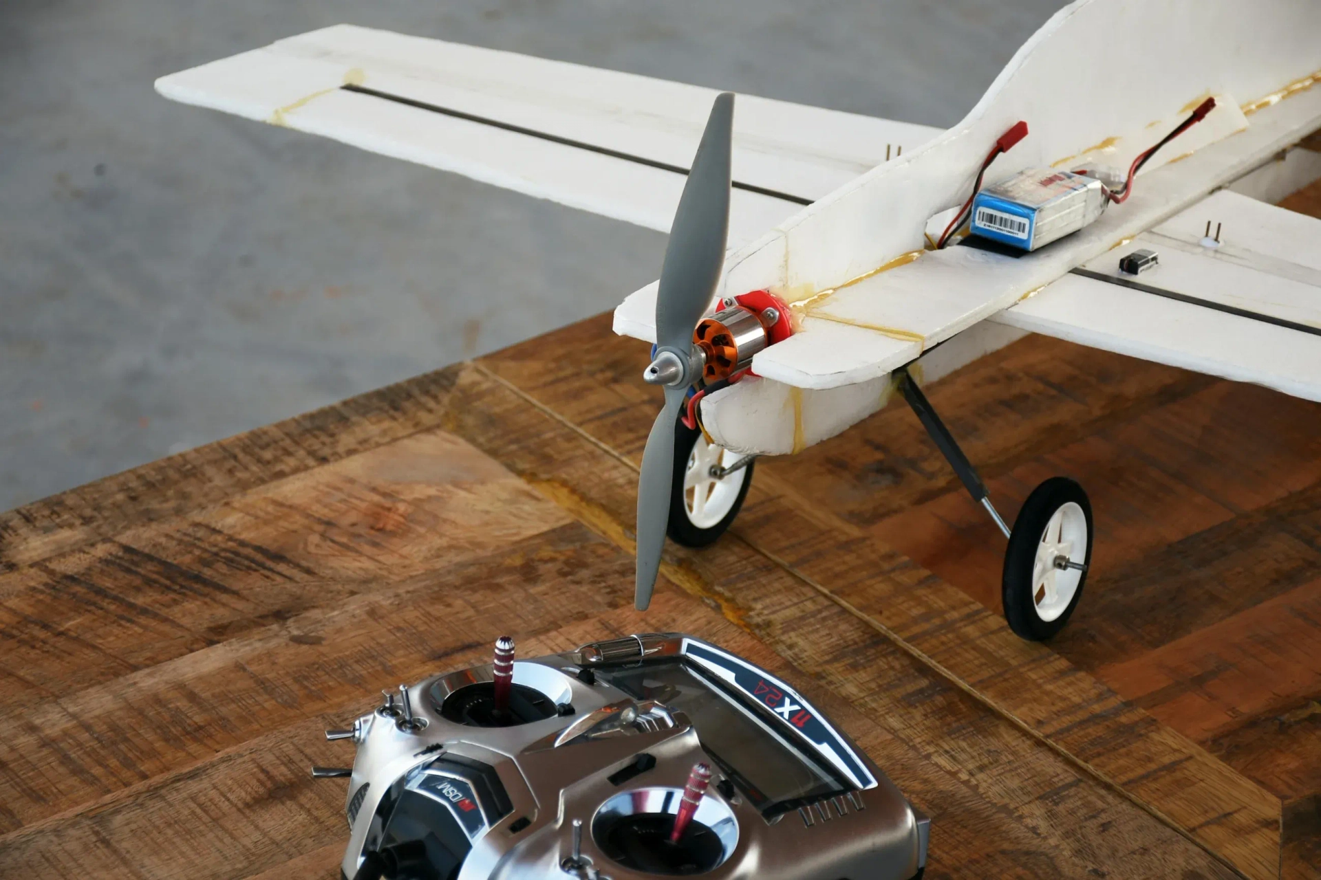
4. Control Linkages and Mechanisms in RC Aircraft
To move a control surface, RC planes rely on a system of servos, pushrods, horns, and cables. This section explains how these components work together.
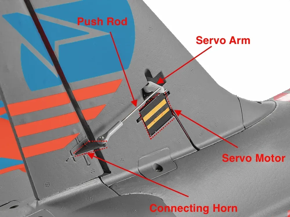
Pushrods and Control Horns
- Pushrods: Rigid rods (metal, carbon, or plastic) that connect the servo arm to the control horn.
- Control Horns: Mounted on the control surface; act as the lever for motion.
- Linkage Ratio: The servo-to-horn distance affects how much a surface moves relative to the servo arm’s motion.
Pull-Pull Cable Systems
- Common for rudders in larger or aerobatic planes.
- Two cables run in opposite directions, each pulling the surface when activated.
- Provides smoother motion with less weight and play over long distances.
Servo Selection Guidelines
- Torque: Choose based on surface size and aerodynamic load.
- Speed: Faster servos improve response in aerobatic models.
- Voltage Compatibility: High-voltage servos pair better with LiPo systems.
- Type:
- Digital servos: More precise and stable.
- Analog servos: Lower cost, suitable for simpler setups.
Adjusting Throw Limits
- Mechanical: Change linkage lengths or hole positions on the servo/control horn.
- Electronic: Use transmitter settings to fine-tune neutral points and max deflection.
9g Micro Servo for RC Planes

Push rod

Connecting horns

Final Thoughts
Control surfaces are the essential tools that give aircraft their maneuverability and stability in flight. The primary control surfaces are vital for any aircraft to fly, while secondary surfaces and mechanical systems improve safety, efficiency, and performance.
For RC pilots, understanding how pushrods, servos, linkage geometry, and transmitter settings interact with aerodynamic surfaces is key to building and flying more responsive, capable aircraft. Whether you're tuning a trainer for stability or pushing a 3D aerobat to its limits, mastering control surfaces is where engineering meets flight.
Related Topics:
The tail section of an airplane plays a critical role in the stability, control, and performance of the aircraft. Whether you're building a foam RC model or designing a full-scale airplane, understanding tail configurations helps you make informed decisions about flight characteristics like yaw control, pitch stability, and aerodynamic efficiency
Dihedral wing design is a foundational element in aircraft stability engineering. By angling the wings upward, designers introduce a natural restoring force that improves roll stability and helps maintain level flight. This makes dihedral ideal for aircraft where ease of control and passive stability are important, such as gliders, UAVs, and training platforms

The Center of Gravity (CG) is the point where the total weight of the airplane is considered to act. It’s the balance point—just like balancing a ruler on your finger. In aviation, getting the CG in the correct location is critical for stable and safe flight. If the CG is off, the aircraft can become unstable, hard to control, or even unflyable
Or you can explore other categories
Electronics