
Comprehensive Guide to Understanding LEDs
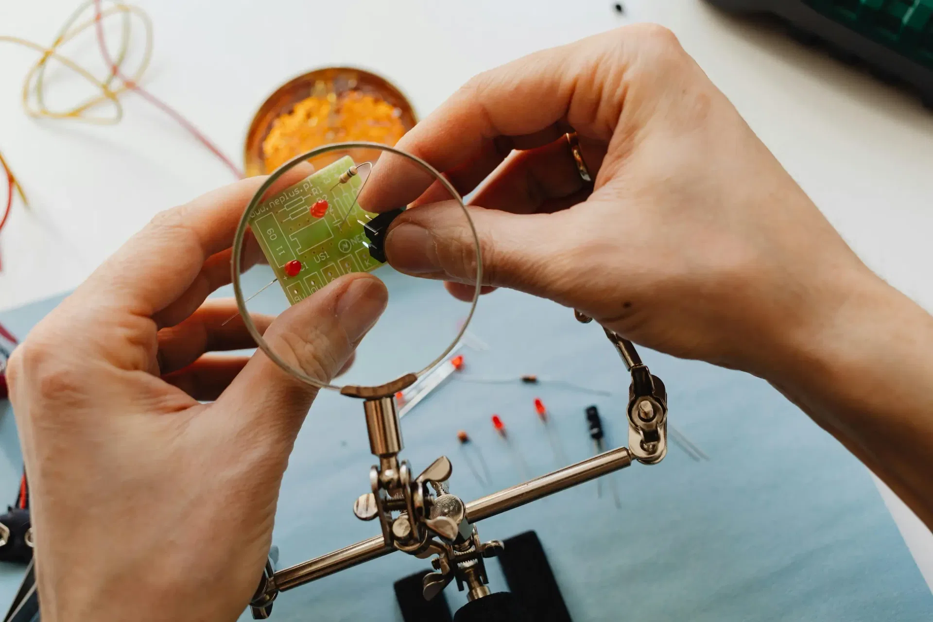
Indicator Light Emitting Diodes (LEDs) are small, low-power LEDs commonly used in electronic devices to signal power status, mode selection, or other visual indications. This article explores the fundamental aspects of indicator LEDs, including their pin configuration, identification of anode and cathode, correct circuit connection, current protection methods, and more.
1. Pin Configuration of Indicator LEDs
Indicator LEDs typically have two pins:
- Anode (+): The longer leg, which connects to the positive voltage.
- Cathode (-): The shorter leg, which connects to ground (GND). Some LEDs may have a flat edge on the cathode side for additional identification.
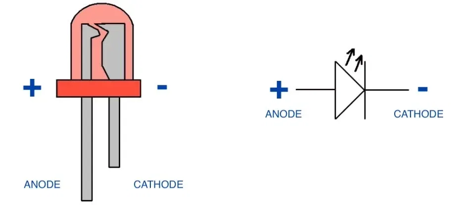
2. How to Identify Cathode from Anode
- The longer leg is the anode (+), and the shorter leg is the cathode (-).
- A flat edge on the LED body indicates the cathode.
- Using a multimeter in diode mode: The positive probe on the anode and negative on the cathode will show a small voltage drop (~1.8V-3.3V depending on the LED color).
Note: If both pins are of the same length, for example, due to trimming, you can identify the cathode by looking inside the LED. The larger internal structure is usually the cathode, while the smaller structure is the anode.
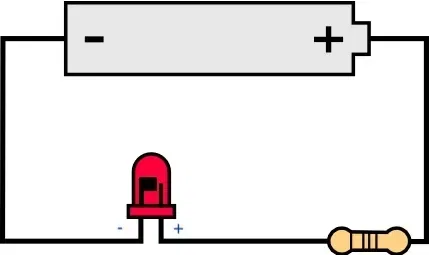
3. How to Connect an LED to a Circuit in Correct Configuration
To ensure proper operation:
- Connect the anode to the positive voltage source.
- Connect the cathode to ground through a current-limiting resistor to prevent excessive current flow.
- Ensure the polarity is correct to avoid a non-functional LED.
Note: the location of the resistor is not important, the configuration will work if the resistor was placed on either side of the LED
4. Protecting LEDs from Excessive Current
Excessive current can damage LEDs, causing overheating or failure. Protection methods include:
- Series Resistor: A resistor in series with the LED to limit current.
- Constant Current Source: For precise current control in advanced circuits
Why Each LED Needs Its Own Resistor
When connecting multiple LEDs in parallel, each LED should have its own individual current-limiting resistor rather than sharing a single resistor. Here’s why:
LEDs Have Different Forward Voltages (Vf):
Even if LEDs are from the same batch, they have slight variations in their forward voltage (e.g., one might be 2.0V while another is 2.1V). If you use a single resistor for all LEDs in parallel, the LED with the lowest Vf will draw more current, possibly overloading and burning out.
Uneven Current Distribution:
LEDs are not perfect resistors; their current is exponential with voltage. The first LED that gets slightly more current heats up, lowering its Vf further, drawing even more current, leading to thermal runaway.
Failure Risk:
If one LED fails (burns out or shorts), the remaining LEDs will receive more current, potentially damaging them.
Best Practice: One Resistor Per LED Each LED should have its own current-limiting resistor. This ensures:
- Stable brightness across all LEDs
- No excessive current on any single LED
- Longer LED lifespan
When Can You Use One Resistor for Multiple LEDs?
- If LEDs are in series, they share the same current, so one resistor can work.
- If you use a current source instead of a resistor (e.g., a constant current driver), you can drive multiple LEDs in parallel.
For best performance and reliability, always use one resistor per LED when wiring LEDs in parallel.
Excessive current can damage LEDs, causing overheating or failure. Protection methods include:
- Series Resistor: A resistor in series with the LED to limit current.
- Constant Current Source: For precise current control in advanced circuits.
Can an LED be Connected Without a Resistor?
In most cases, an LED should not be connected directly to a power source without a current-limiting resistor, as excessive current can damage it. However, there are exceptions:
- Using a Button Battery: Small coin cell batteries (e.g., CR2032) have limited current output and can safely power an LED without a resistor for short durations.
- LEDs with Built-in Resistors: Some LEDs come pre-configured with an internal resistor, making external resistors unnecessary.
- Current-Limited Power Sources: Some circuits, like microcontroller GPIO pins, have internal resistance limiting current to safe levels. Excessive current can damage LEDs, causing overheating or failure. Protection methods include:
5. Choosing the Correct Value of a Protection Resistor
To select an appropriate resistor, use Ohm’s Law:
where:
- R = Resistor value (Ω)
- Vsupply = Supply voltage (V)
- VLED = Voltage drop across the LED (V)
- ILED = Desired current (A)
Example:
For a 5V power supply and a red LED (1.8V drop) with a desired 10mA current:
Choose a standard resistor value (e.g., 330Ω).
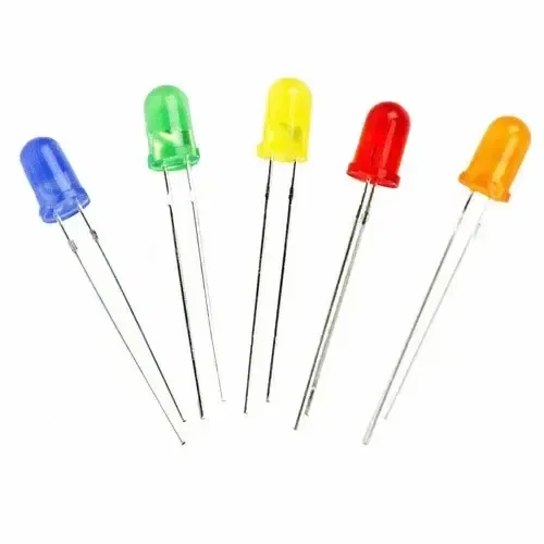
6. Voltage Drop Across LEDs for Different Colors
The forward voltage drop depends on the LED color:
- Red: ~1.8V – 2.2V
- Yellow: ~2.0V – 2.4V
- Green: ~2.0V – 3.0V
- Blue: ~3.0V – 3.5V
- White: ~3.0V – 3.5V
7. Maximum Current for LEDs of Different Colors
Different LED colors have varying maximum current ratings:
- Red: 10-20mA
- Yellow: 10-20mA
- Green: 10-30mA
- Blue/White: 10-30mA (higher-power variants may require more)
So we can conclude that 15mA seems to be the best value that best works for all LEDs for general applications
8. How to Test an LED Using a Multimeter
To determine if an LED is functioning properly:
- Using Diode Mode:
- Set the multimeter to diode test mode.
- Connect the positive (red) probe to the anode and the negative (black) probe to the cathode.
- A functional LED will light up faintly, and the multimeter will display a voltage drop (~1.8V-3.5V depending on color).
- If no light appears and the meter shows OL (open loop), the LED may be defective.
- Using Resistance Mode:
- Set the multimeter to resistance mode (Ω symbol).
- Connect the probes as in diode mode.
- A high resistance reading in both directions indicates a faulty LED.
- Testing an LED While Connected to a Circuit: If the LED is part of a circuit, testing it directly with a multimeter may give misleading results due to other components influencing the measurement. In such cases:
- Disconnect one leg of the LED from the circuit and test it separately.
- Ensure the circuit is powered off before testing to avoid damage to the multimeter.
- If testing in-circuit is necessary, measure the voltage drop across the LED while it is powered to check for expected values.
To determine if an LED is functioning properly:
- Using Diode Mode:
- Set the multimeter to diode test mode (symbol: ➳|).
- Connect the positive (red) probe to the anode and the negative (black) probe to the cathode.
- A functional LED will light up faintly, and the multimeter will display a voltage drop (~1.8V-3.5V depending on color).
- If no light appears and the meter shows OL (open loop), the LED may be defective.
- Using Resistance Mode:
- Set the multimeter to resistance mode (Ω symbol).
- Connect the probes as in diode mode.
- A high resistance reading in both directions indicates a faulty LED.
This simple test ensures the LED is working before integrating it into a circuit.
Conclusion
Indicator LEDs are essential components in electronics, providing visual feedback. Understanding their pin configuration, proper connection, and current protection techniques ensures reliable operation and longevity. Proper resistor selection and knowledge of voltage drops help design efficient circuits for various applications.
Related Topics:
Learn about transistors, their types, functions, and applications in modern electronics. Discover how BJTs, FETs, MOSFETs, and more are used in amplification, switching, and power control.
Discover the fundamentals of diodes, their types, functions, and applications in electronics. Learn how diodes are used in power rectification, voltage regulation, signal processing, and more.
Resistors are key in electronics, from LED circuits to advanced projects. This guide covers their function, types, identification, and a relatable analogy to simplify learning.
Or you can explore other categories
Electronics