7-Segment Displays

7-Segment Displays Explained: From Basics to Arduino Projects
1. Introduction
From digital clocks and calculators to microwave ovens and measuring instruments, 7-segment displays are everywhere. They offer a simple, efficient way to display numeric information using just a few LEDs arranged in a specific pattern. While they might seem straightforward, working with them in digital circuits—especially when interfacing with microcontrollers like Arduino—brings some interesting challenges and techniques. This article explores how 7-segment displays work, common chips and modules used, and how to connect and cascade them for use in practical projects.
2. What Is a 7-Segment Display?
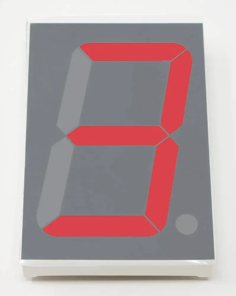
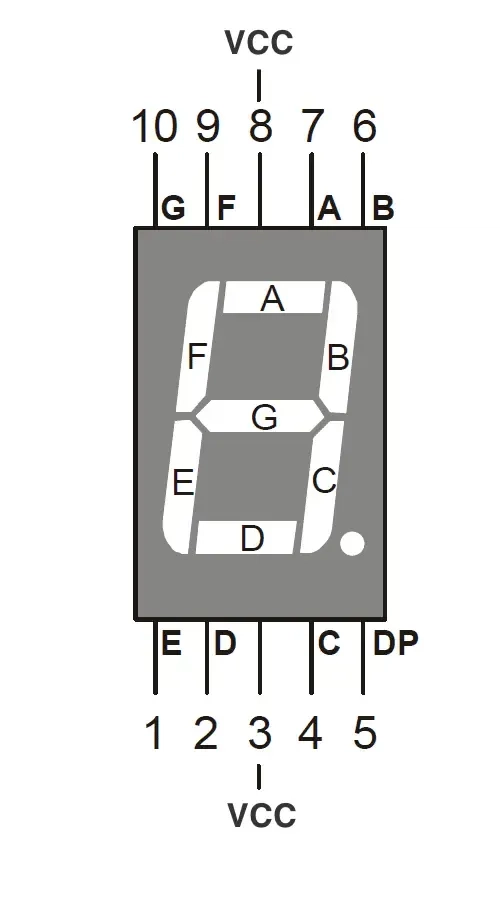
A 7-segment display is an arrangement of seven LEDs (plus an optional decimal point) labeled segments a through g, designed to form numbers and a few letters when lit in different combinations. Each segment can be controlled independently.
Types of 7-Segment Displays
- Common Cathode (CC): All cathodes of the LEDs are connected together. Segments light up when their individual anode pins are set HIGH.
- Common Anode (CA): All anodes are connected together. Segments light up when their individual cathode pins are set LOW.
BS vs AS Display Families
When selecting a 7-segment display, pay attention to the part number suffix, as it often indicates the display's internal configuration:
- BS family: These displays are typically Common Anode. For example, the popular 5161BS and 3461BS-1 are both Common Anode types.
- AS family: These are usually Common Cathode displays. An example would be the 5161AS, which looks nearly identical to the BS variant but requires opposite logic to control.
Tip: Always consult the data sheet to confirm the exact type before wiring — misidentifying the display type could result in reversed logic or no output at all.
3. Internal Composition
Each 7-segment digit contains 7 LEDs arranged to form the number "8", plus an optional decimal point (DP). In a common anode display, the positive terminals of all LEDs are tied together. You control each segment by grounding its corresponding cathode pin.
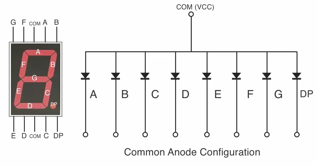
Common Anode (CA): All anodes are connected together.
Segments light up when their individual cathode pins are set LOW.
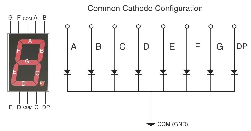
- Common Cathode (CC): All cathodes of the LEDs are connected together.
Segments light up when their individual anode pins are set HIGH.
4. Popular 7-Segment Display Modules and Chips
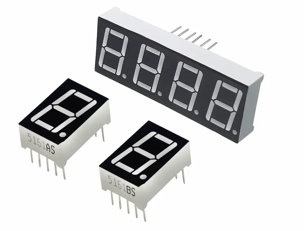
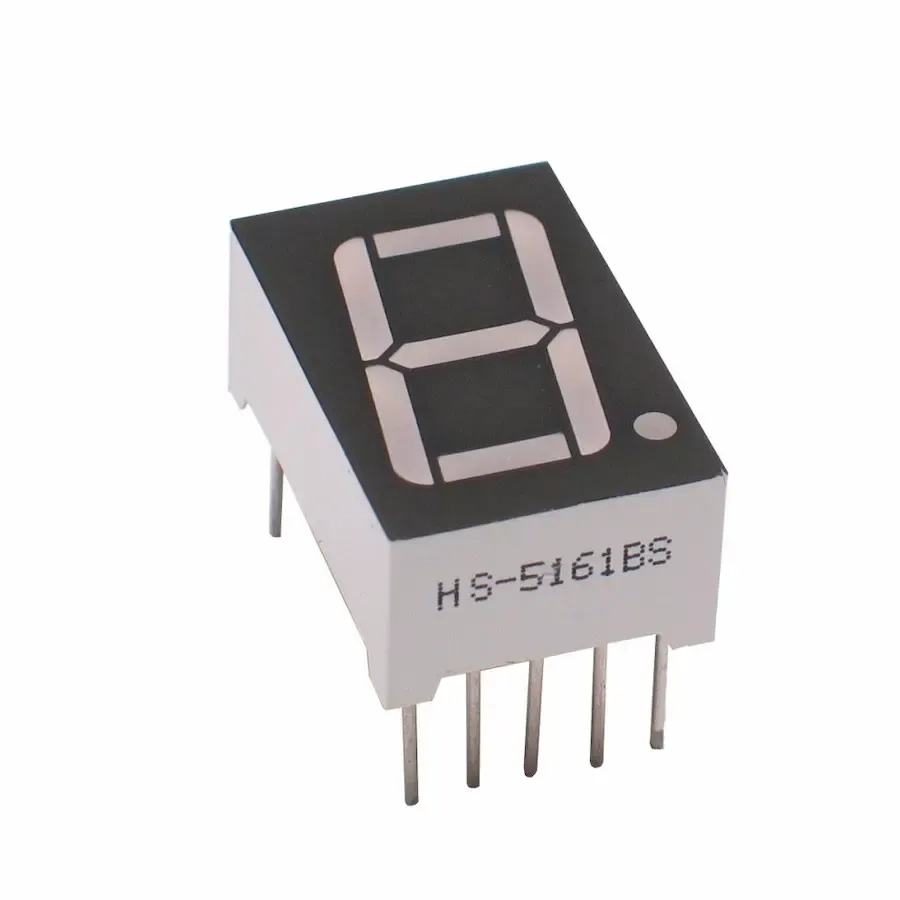
4.1 5161BS Single-digit display
Type: Single-digit 7-segment display.
Configuration: Common Anode
Pin Count: 10 (7 segments + decimal point + 2 anodes)
Wiring Notes:
- Connect both common anode pins (usually pins 3 and 8) to VCC (typically 5V).
- Even though they are internally connected, connecting both pins externally ensures better current distribution and reduces voltage drop across internal traces.
- This improves reliability, prevents flickering or dim segments, and ensures even power distribution when multiple segments are active.
- Each segment is controlled by pulling its cathode pin LOW.
- Use current-limiting resistors (220Ω–330Ω) to protect each segment.
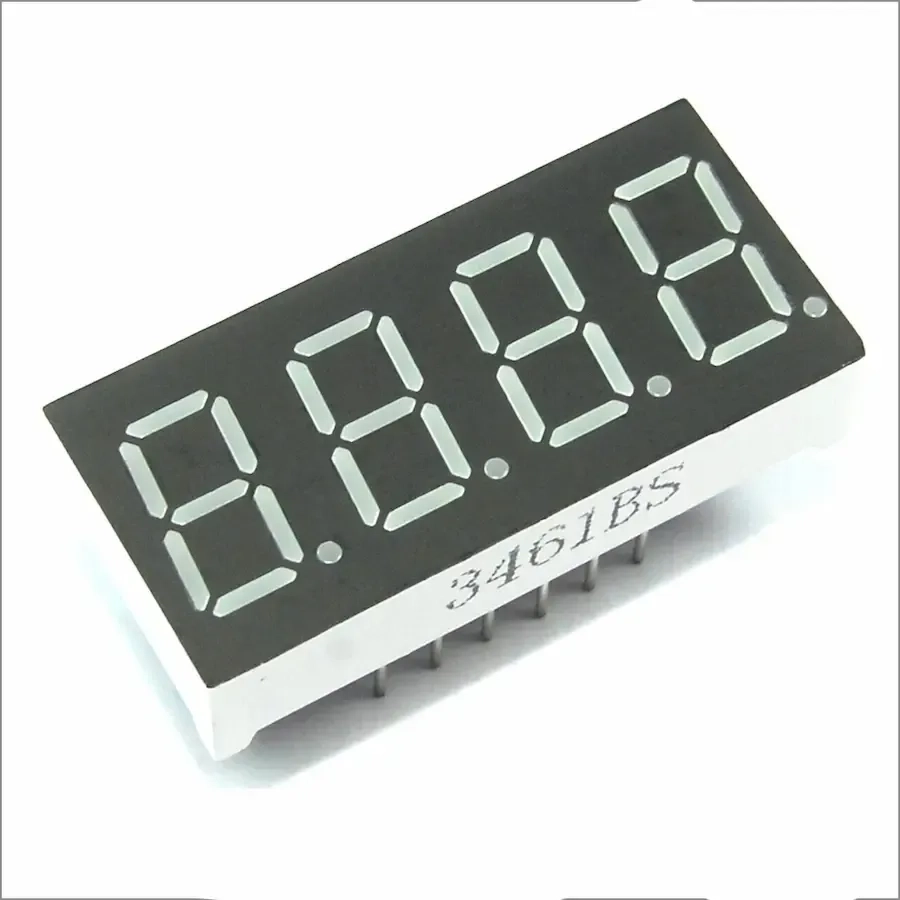
4.2 3461BS-1 four-digit display
Type: 4-digit 7-segment display.
Configuration: Common Anode
Pin Count: 12–16
Wiring Notes:
- All digits share segment lines (a–g, dp).
- Each digit has its own common anode pin.
- To display numbers, multiplexing is needed — lighting one digit at a time in rapid succession.
4.3 I2C-Based 7-Segment Displays
Some modern 7-segment displays are manufactured with built-in I2C interfaces, making them especially convenient for microcontroller projects. These modules integrate a controller chip that handles all segment driving and multiplexing internally, exposing only simple I2C commands for communication.
Common Examples:
- HT16K33 modules (used by Adafruit and others)
- TM1637 modules (uses a 2-wire protocol similar to I2C)
Benefits:
- Only two microcontroller pins required: SDA and SCL.
- Simplified wiring, ideal for compact or beginner-friendly setups.
- No need to manage segment logic or multiplexing manually.
- Many libraries exist (e.g., Adafruit_LEDBackpack, TM1637Display) to support these modules.
Considerations:
- Slightly more expensive than basic displays.
- Some modules may have fixed or limited address configuration for I2C chaining.
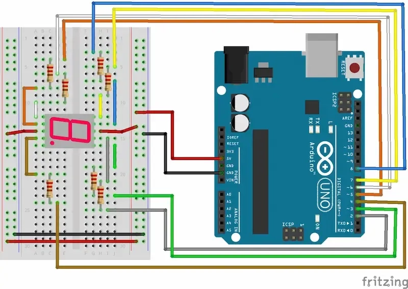
5. How to Connect a 7-Segment Display to Arduino (Step-by-Step)
Direct Wiring for 5161BS
- Use 8 Arduino digital pins for segments (a–g + dp if needed).
- Connect both common anode pins to 5V.
- Add 220Ω resistors between Arduino and each segment pin.
- Use digitalWrite(segmentPin, LOW) to light up a segment.
Code Example
1// Pin mapping for segments a to g2const int segmentPins[7] = {2, 3, 4, 5, 6, 7, 8};34// Segment byte map: gfedcba5const byte digitPatterns[10] = {6 0b00111111, // 07 0b00000110, // 18 0b01011011, // 29 0b01001111, // 310 0b01100110, // 411 0b01101101, // 512 0b01111101, // 613 0b00000111, // 714 0b01111111, // 815 0b01101111 // 916};1718void setup() {19 // Set all segment pins as outputs20 for (int i = 0; i < 7; i++) {21 pinMode(segmentPins[i], OUTPUT);22 }23}2425void loop() {26 for (int digit = 0; digit < 10; digit++) {27 displayDigit(digit);28 delay(1000); // 1 second delay29 }30}3132// Function to display a digit (0–9)33void displayDigit(int digit) {34 byte pattern = digitPatterns[digit];35 for (int i = 0; i < 7; i++) {36 // Common anode: LOW = ON, HIGH = OFF37 bool segmentOn = pattern & (1 << i);38 digitalWrite(segmentPins[i], segmentOn ? LOW : HIGH);39 }40}41
6. Practical Tips
- Always use current-limiting resistors (220Ω–330Ω) per segment for raw LED displays.
- Know your display's type (CA or CC) before wiring.
- I2C displays are easiest to use, while raw LED displays give more control and learning value.
- Avoid powering large displays directly from microcontroller pins.
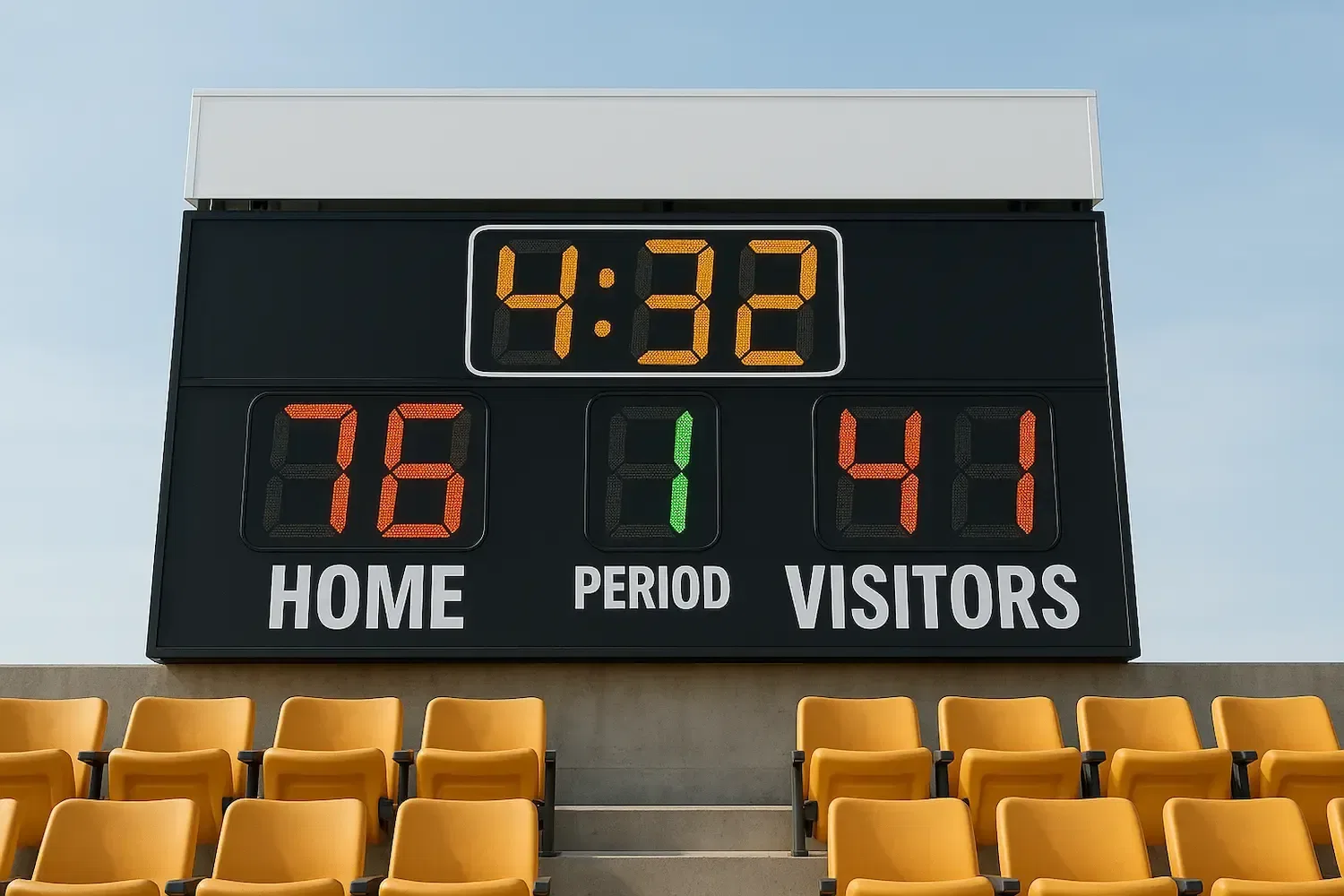
Note on Large 7-Segment Displays
Large 7-segment displays, like those used in scoreboards or industrial signs, work on the same basic principle as smaller ones. However, they require higher power and voltage, and often need transistors, MOSFETs, or relay drivers to handle the current. These displays are usually powered by an external DC power supply.
For ease of integration, many commercial large-digit displays come with built-in serial interfaces such as RS-232, RS-485, Modbus, or I2C, allowing them to be controlled easily from microcontrollers or PLCs.
Conclusion
7-segment displays may be simple, but mastering their use opens the door to creating clocks, voltmeters, digital counters, and more. Whether you're lighting up one digit or controlling a dozen with a shift register, I2C driver, or prebuilt module, the principles are foundational for digital electronics.
Related Topics:
Discover the fundamentals of diodes, their types, functions, and applications in electronics. Learn how diodes are used in power rectification, voltage regulation, signal processing, and more.
Resistors are key in electronics, from LED circuits to advanced projects. This guide covers their function, types, identification, and a relatable analogy to simplify learning.
This article explores the fundamental aspects of indicator LEDs, including their pin configuration, identification of anode and cathode, correct circuit connection, current protection methods, and more
Or you can explore other categories
Electronics