Push Buttons in Digital Circuits


Connecting Push Buttons to Digital Circuits and Arduino
Introduction
Push buttons are among the most essential and widely used components in electronics. Whether it’s starting a program, toggling a device, or navigating a menu, push buttons allow human interaction with digital circuits. In this article, we’ll walk you through how to connect push buttons to microcontrollers like Arduino, explain pull-up/down resistors, explore switch debouncing, and provide a practical example with clean, structured Arduino code.
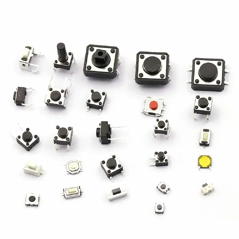
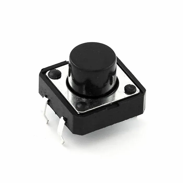
What Is a Push Button?
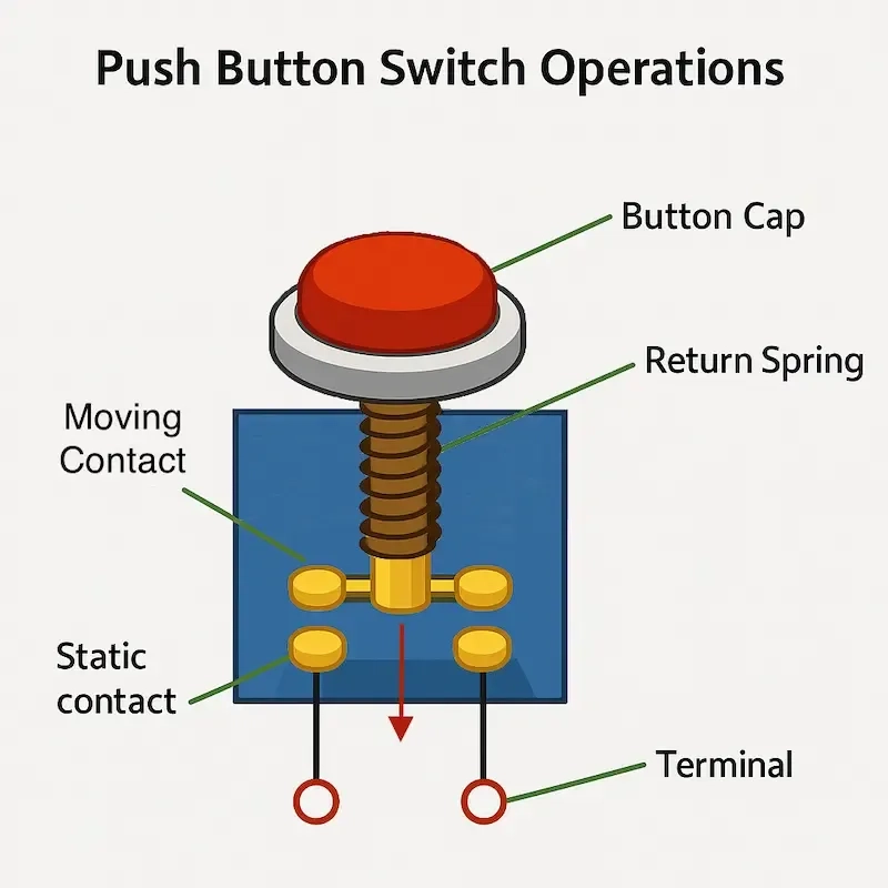
A push button is a mechanical switch that temporarily completes or breaks an electrical connection when pressed. Typically, they are normally open (NO), meaning the circuit is open until the button is pressed.
When used with microcontrollers, buttons are connected to input pins that detect voltage levels — either HIGH (1) or LOW (0) — based on how the button is wired.
Pull-Up vs Pull-Down Resistors
A digital input pin must be connected to a known voltage when idle. If left floating (disconnected), it may randomly read HIGH or LOW due to electrical noise. Pull-up and pull-down resistors ensure the input pin has a stable logic level when the button is not pressed.
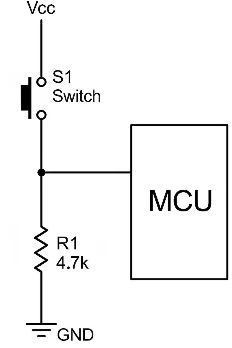
Pull-Down Configuration
- Wiring: One side of the button to 5V, the other to the input pin, with a resistor to GND.
- Behavior:
- Button not pressed: pin reads LOW.
- Button pressed: pin reads HIGH.
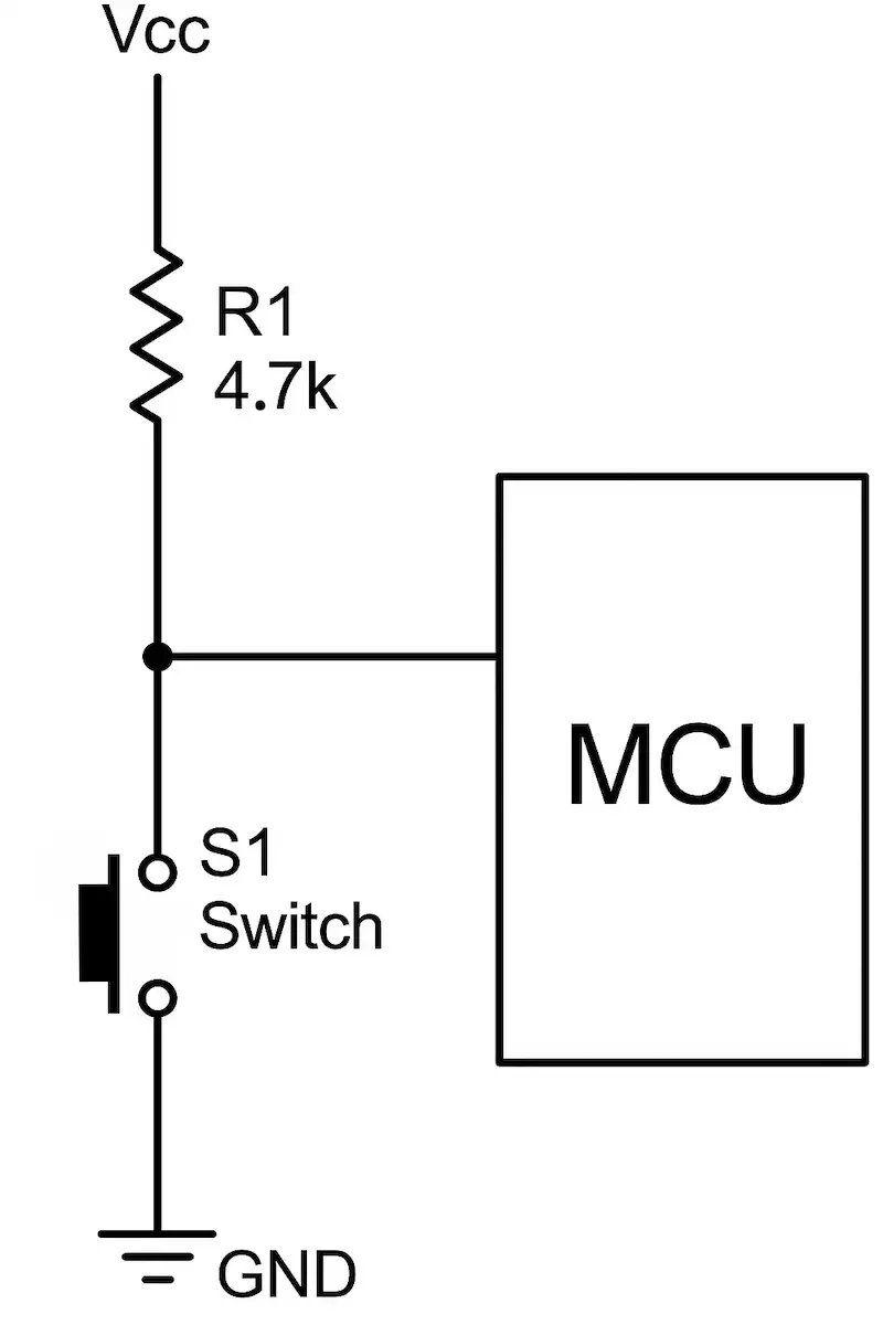
Pull-Up Configuration
- Wiring: One side of the button to GND, the other to the input pin, with a resistor to 5V.
- Behavior:
- Button not pressed: pin reads HIGH.
- Button pressed: pin reads LOW.
This is the preferred method for Arduino projects because Arduino has internal pull-up resistors.
Using Internal Pull-Up Resistors in Arduino
Arduino simplifies pull-up configuration by allowing you to enable an internal pull-up resistor via code:
1pinMode(buttonPin, INPUT_PULLUP);
This removes the need for an external resistor. In this configuration, the button is connected between the input pin and GND.
Choosing the Right Resistor Value
If using external resistors:
- Typical value: 10kΩ
- Lower than 4.7kΩ: wastes current.
- Higher than 50kΩ: might result in weak logic levels.
10kΩ is a common and reliable choice.

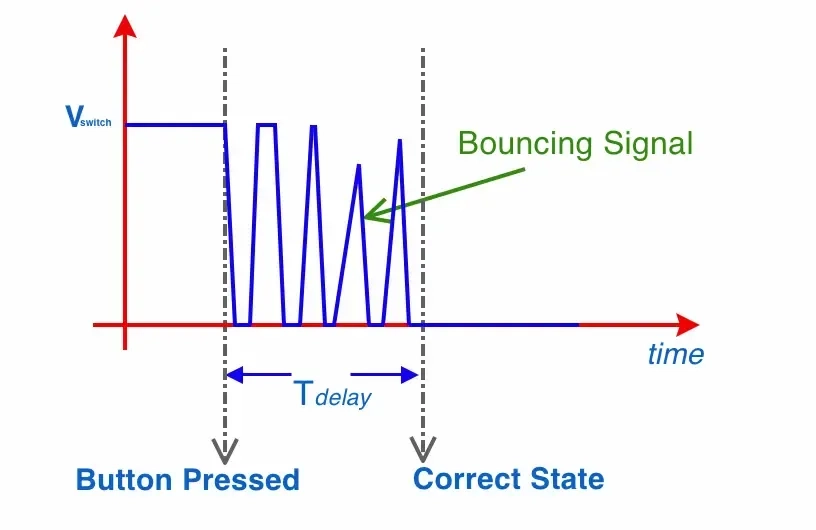
What Is Switch Debouncing?
When a button is pressed or released, its contacts mechanically bounce for a few milliseconds. This bounce causes the input signal to rapidly fluctuate, which digital systems might interpret as multiple presses.
How to Handle Debouncing
To avoid false or repeated triggering from a single press, debouncing techniques are used.
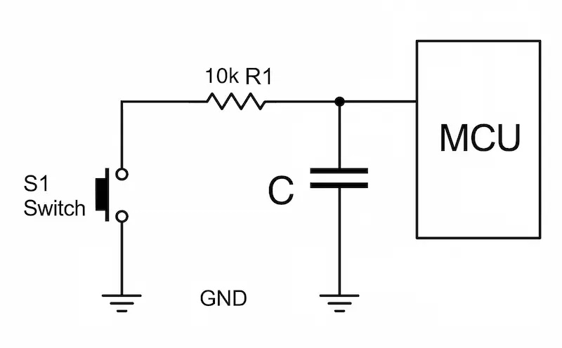
Option 1: Hardware Debouncing
A basic RC (Resistor-Capacitor) circuit can be added to filter out the bouncing. This smooths the voltage change at the input pin.
Example Circuit:
- Place a 10kΩ resistor between the button and the digital input pin.
- Connect a 100nF capacitor from the input pin to GND.
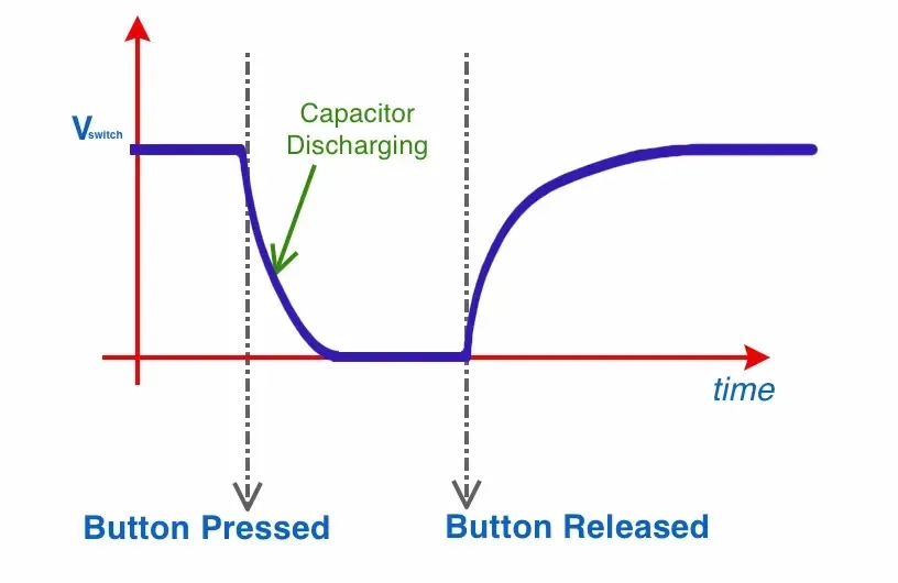
This setup absorbs the fast voltage fluctuations caused by bouncing, ensuring that the pin voltage rises and falls smoothly.
Hardware debounce is simple and effective, especially when microcontroller resources are limited.
Option 2: Software Debouncing
This method uses a short time delay in the code to filter out bouncing effects. It’s more flexible and doesn’t require extra components.
The microcontroller waits for a fixed period (e.g., 50 milliseconds) after detecting a change in button state before considering the change valid.
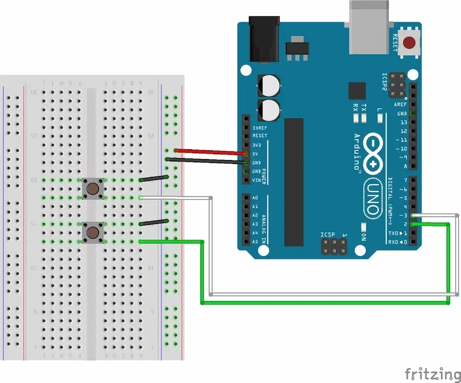
Example: Button Counter with Reset — Using Structured Code
This practical example uses two push buttons connected to an Arduino:
- Button A (on pin 2): Increments a counter.
- Button B (on pin 3): Resets the counter to 0.
We’ll explain both the circuit wiring and the code logic.
Circuit Description
Each push button is connected using the internal pull-up resistor configuration.
Wiring Details:
- Button A:
- One leg connected to Arduino digital pin 2
- Other leg connected to GND
- Button B:
- One leg connected to Arduino digital pin 3
- Other leg connected to GND
Since we use INPUT_PULLUP in code, the default logic is:
- Not pressed → HIGH (pulled up by resistor)
- Pressed → LOW (shorted to GND)
This is completely safe and common practice in Arduino digital input design.
Arduino Code (with Explanation Below)
1const int buttonA = 2;2const int buttonB = 3;34const unsigned long debounceDelay = 50;5int counter = 0;67// Structure to track each button's state and debounce timing8struct Button {9 int pin;10 int lastState;11 unsigned long lastDebounceTime;12};1314Button btnA = {buttonA, HIGH, 0};15Button btnB = {buttonB, HIGH, 0};1617void setup() {18 pinMode(btnA.pin, INPUT_PULLUP);19 pinMode(btnB.pin, INPUT_PULLUP);20 Serial.begin(9600);21}2223bool debounce(Button &btn) {24 int reading = digitalRead(btn.pin);25 bool pressed = false;2627 if (reading != btn.lastState) {28 btn.lastDebounceTime = millis(); // Reset debounce timer29 }3031 if ((millis() - btn.lastDebounceTime) > debounceDelay) {32 // Check for falling edge (HIGH to LOW)33 if (reading == LOW && btn.lastState == HIGH) {34 pressed = true;35 }36 }3738 btn.lastState = reading;39 return pressed;40}4142void loop() {43 if (debounce(btnA)) {44 counter++;45 Serial.print("Count: ");46 Serial.println(counter);47 }4849 if (debounce(btnB)) {50 counter = 0;51 Serial.println("Counter Reset");52 }53}54
Code Explanation
- Struct Button: Groups each button’s pin, lastState, and debounce timing.
- Function debounce():
- Detects changes in state.
- Waits 50 ms to see if state is stable (no bouncing).
- Only returns true if the button was just pressed (a falling edge).
- In loop():
- If Button A is pressed, counter is incremented and displayed.
- If Button B is pressed, counter is reset and a message is printed.
Output in Serial Monitor
When viewed in the Arduino Serial Monitor, the result looks like:
1Count: 12Count: 23Count: 34Counter Reset5Count: 16...7
Each press is counted once, even if your finger bounces. The reset button clears the counter immediately.
Summary
- Push buttons are simple but powerful components in digital systems.
- Always use pull-up or pull-down resistors to avoid floating input pins.
- Arduino’s INPUT_PULLUP makes wiring easy by using internal resistors.
- Debouncing is essential to avoid false signals from mechanical bounce.
- Hardware debounce uses an RC filter to smooth input.
- Software debounce uses timing logic to detect valid presses.
- Structured code helps keep multi-button logic clean and maintainable.
Related Topics:
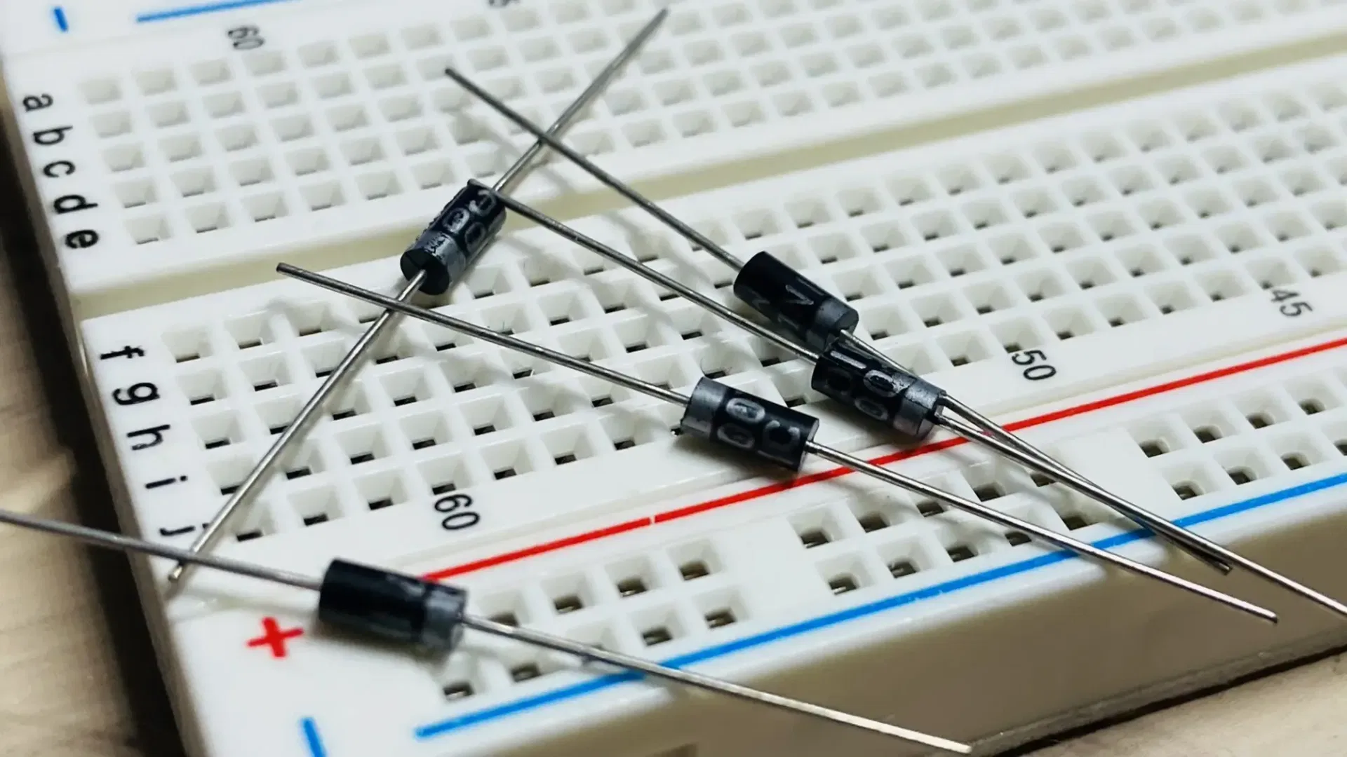
Discover the fundamentals of diodes, their types, functions, and applications in electronics. Learn how diodes are used in power rectification, voltage regulation, signal processing, and more.
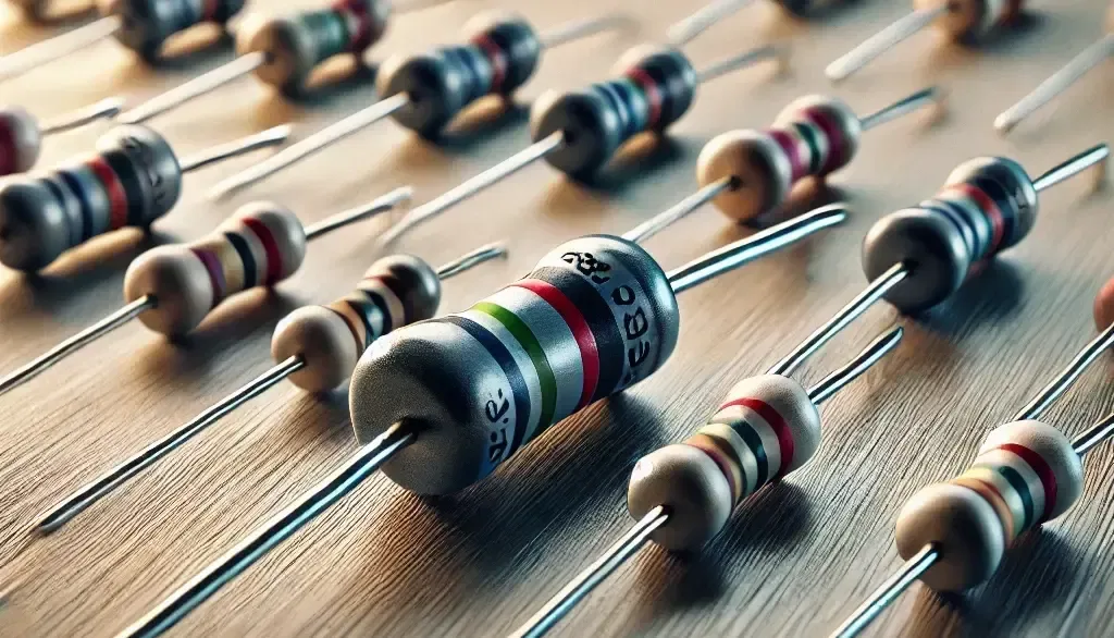
Resistors are key in electronics, from LED circuits to advanced projects. This guide covers their function, types, identification, and a relatable analogy to simplify learning.

This article explores the fundamental aspects of indicator LEDs, including their pin configuration, identification of anode and cathode, correct circuit connection, current protection methods, and more
Or you can explore other categories

Electronics