How I Calibrated My Hotwire for Foam Cutting

How I Calibrated My Hotwire for Foam Cutting: A Step-by-Step DIY Guide
A Practical Setup for RC Airplane Builders and Makers
If you’ve ever tried building your own hot-wire foam cutter but found yourself stuck choosing the right power adapter or getting the wire just hot enough to cut—without burning through your foam—you’re not alone. In this article, I break down the essential concepts behind setting the correct voltage and current for your hot-wire cutter. Through hands-on testing with Nichrome wire, simple materials, and an adjustable power supply, I set out to find the most efficient setup for smooth, precise cuts—without overheating or wasting power.
Important Safety Disclaimer:
Nichrome hot-wires can reach temperatures of up to 1200 °C (2200 °F) in open air. These temperatures are more than enough to cause severe burns instantly on contact. Always handle your setup carefully. Never touch the wire while powered or immediately after power is turned off, as it may remain hot for several seconds. Keep flammable materials away and ensure your workspace is child-safe and supervised.
⚠️ Important: Cutting or burning foam can release fumes that may be toxic. Always work in a well-ventilated area, and wear a suitable mask or respirator to avoid inhaling harmful vapours.
Materials Used
Here’s what I used for this experiment:
- 60 cm of 28 AWG Nichrome wire (Cr20Ni80)
- Adjustable DC power supply: 30V/ 5A (150 Watts)
- Two alligator clips
- Stainless steel tension spring
- Wooden base: 15 cm × 60 cm × 2.5 cm
- Styrofoam block
- 2 × Self-tapping stainless screws (40 mm)
- Ruler, Pliers, Screw Driver and a tying wire

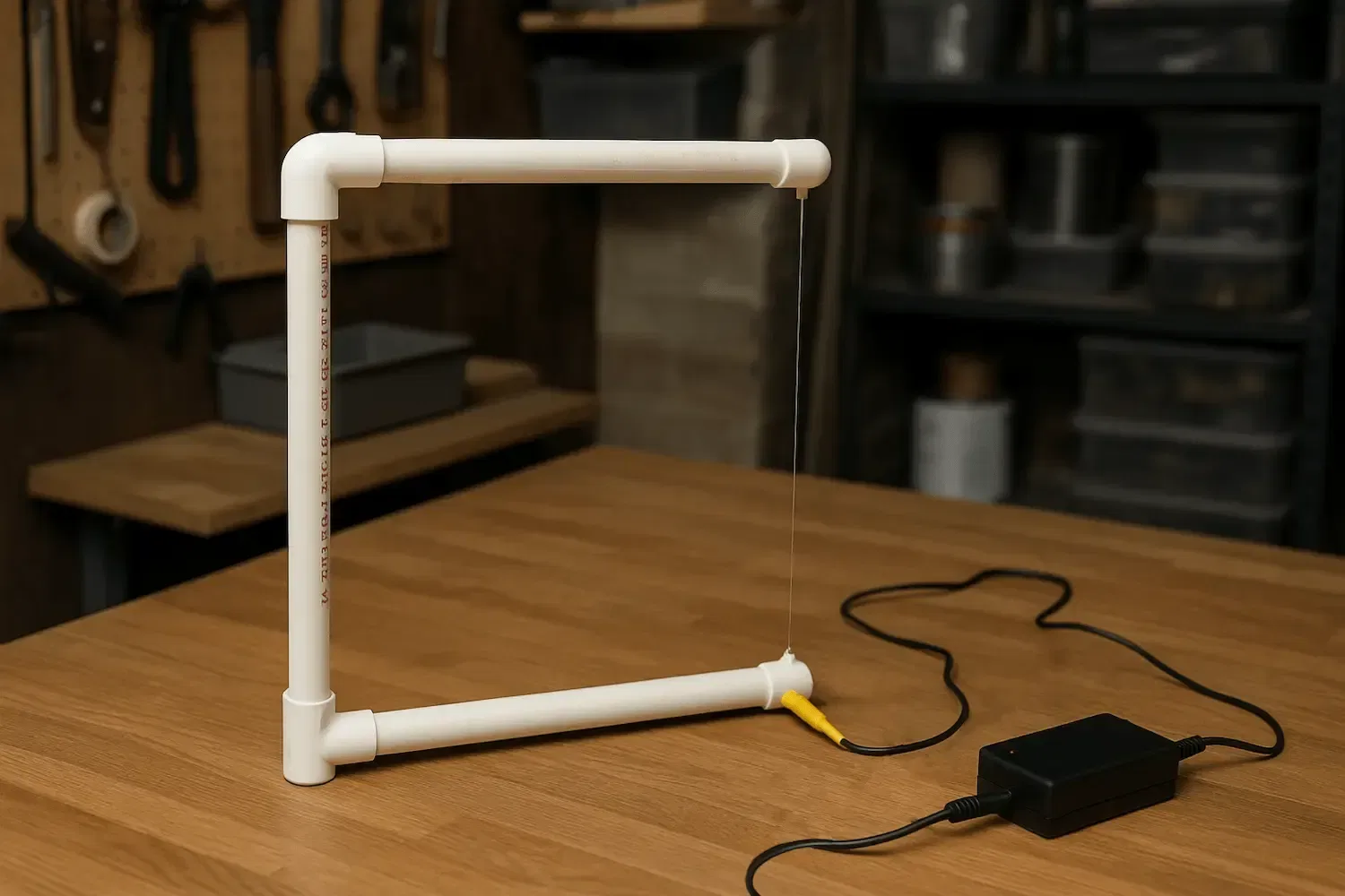
Building the Hotwire Rig
- Fixed two screws 50 cm apart in the wooden base
- Attached a tension spring to one screw using tying wire
- Connected one end of the Nichrome wire to the spring and the other end to the second screw — ensuring the wire was taut but flexible
The stainless steel tension spring plays a critical role: as the Nichrome wire heats up, it expands slightly, which would otherwise cause the wire to sag or loosen. The spring automatically compensates for that expansion, keeping the hotwire under consistent tension throughout the cut. This helps maintain straight cuts and prevents the wire from bending or warping mid-operation.
This setup, combined with the use of alligator clip cables, gave me the flexibility to connect the power supply to any section of the wire, allowing me to experiment with different active lengths of the wire without the need to cut it or rewiring the whole rig.


Measuring Nichrome Resistance
What Is Nichrome Wire?
Nichrome is a metal alloy primarily composed of Nickel (Ni) and Chromium (Cr). It’s commonly used as a heating element thanks to its unique combination of properties:
- High electrical resistance, much greater than copper or aluminum
- Excellent heat tolerance, retaining strength and stability at elevated temperatures
- Strong resistance to oxidation, allowing it to operate in air without burning out quickly
These characteristics make Nichrome perfect for applications such as toasters, heat guns, and foam cutters. When electric current flows through the wire, its resistance generates heat — ideal for melting and slicing through materials like Styrofoam.
In my experiment, I used Cr20Ni80 Nichrome wire, which consists of 20% Chromium and 80% Nickel. The wire had a gauge of 28 AWG (approximately 0.3 mm in diameter) and a specified resistance of 15.4 ohms per meter.
I began by measuring a 40 cm length of the wire using a digital multimeter. The reading fluctuated around 8.1 ohms, slightly higher than the expected 6.16 ohms. This variation is normal, as standard multimeters often produce unstable and inaccurate readings when measuring low resistance values.
The elevated resistance may also be attributed to the wire being stretched by a spring, which can slightly affect its resistivity.

I then decided to measure the actual resistance of the wire by applying Ohm’s Law, which states that the voltage across a resistor is directly proportional to the current flowing through it. Based on the data sheet, the nominal resistance for 40 cm of this wire was estimated at around 6.16 ohms. I began by applying 3 volts to the wire, expecting a current of no more than 0.49 amps. When I powered it on, the current settled around 0.44 amps, which corresponds to a resistance of approximately 6.8 ohms.
This gave me a reliable reference resistance to use in the following calculations.

Initial Power Test (20 cm Segment)
To play it safe, I began with only 20 cm of Nichrome wire between the alligator clips. I switched on the power supply at 3V and noticed a current draw of 0.90A. This confirmed the resistance range I measured earlier — around 3.33 ohms — matching the expected resistance of the wire at this length (approximate of 3.06 Ohms).
The wire barely heated at this voltage, so I gradually increased the voltage while carefully monitoring the wire’s behaviour. At around 6V, I began feeling noticeable heat along the wire surface.
Testing temperatures was tricky:
- A kitchen thermometer gave inconsistent readings since it wasn’t immersed in any material, and the wire’s contact area was too small
- An infrared (IR) thermometer also failed to give accurate results because the wire was too thin and reflective to measure reliably
Despite these limitations, the physical feel of the heat and the foam’s response became the best indicators to proceed with calibration.

Voltage and current readings at 20cm of NiChrome wire
Finding the Optimal Cutting Temperature
To locate the highest usable temperature, I gradually increased the voltage while ensuring the current stayed below my power supply’s 5 A limit. The wire began to glow faint red at 10.2 V / 2.85 A—already too hot for clean foam cutting. Pushing to 12.4 V / 3.41 A produced a bright red glow, which would melt foam from a distance and leave a messy, wide kerf.
I then stepped the voltage down gradually, testing the cut quality at each stage:
- 9.4 V / 2.62 A – The red glow disappeared, and the wire produced a perfect, clean cut.
- 8.0 V / 2.24 A – Still produced a perfect cut and was more efficient in terms of power.
- 7.0 V / 1.98 A – Cut remained clean, but a slight drag was felt.
- 6.0 V / 1.71 A – The wire could still cut through the foam, but drag became more noticeable.
- 5.0 V / 1.43 A – The drag was significant, and cut quality suffered.
Sweet spot: Between 7 V and 8 V — ideal balance between clean cutting and energy efficiency.
Minimum setting: 7 V at 1.98 A, which equals about 13.86 watts for 20 cm of wire. That’s approximately 6.93 W per 10 cm, or 3.5 V per 10 cm.
Best setting: 7.5 V at 2.11 A, which equals about 15.8 watts for 20 cm of wire. That’s approximately 7.9 W per 10 cm, or 3.75 V per 10 cm.
These current levels are best suited for cutting bulky foam pieces, where consistent heat is needed for smooth progress. However, they are not suitable for cutting foam along a template. Template cutting often requires slowing down at corners and angles, which exposes the foam to heat for longer. At currents above ~1.4 A, this prolonged heating can cause excessive melting and distortion. For template cutting, keep the current closer to 1.4 A or less for best results.
Rule of thumb: You can scale up the wire length as long as you maintain a constant current between 1.98 A and 2.2 A for bulky cuts and around 1.4A for template cutting.

A clean cut using a 20cm wire at 7V/1.98A
Scaling Up to 30 & 40 cm Wire
At this point, I wanted to extend the effective cutting length to 30 cm, so I simply moved one of the alligator clips from the 20 cm mark to 30 cm away from the other clip, leaving the rest of the setup unchanged.
Based on earlier findings—specifically the estimate of 3.5 V per 10 cm—I expected to start around 10.5 V. I set the power supply to 10.5 V / 1.9 A, and the wire performed well: it heated evenly and delivered a smooth, clean cut.
I then repeated the same process to increase the length to 40 cm, setting the voltage to 14 V / 1.92 A, and the wire maintained the same level of performance, cutting efficiently and consistently.
Quick Reference Chart
The following readings are based on my experiments using 28 AWG Nichrome wire. Other wire gauges or wires with different Nickel-to-Chromium ratios may have different resistance values, and therefore require different voltages and power levels for effective cutting. Always recalibrate if you change the wire type.

Note: These values are approximations. Actual performance may vary based on resistance fluctuations, tension, and cooling conditions.
Final Notes and Safety Tips
- Always begin with low voltage and increase gradually
- Keep the wire taut using a spring to handle thermal expansion
- For a clean cut, avoid glowing red wires — moderate heat is sufficient
- Use adjustable power supplies with current limiting features for safety
- Work in a well-ventilated area to avoid inhaling fumes from melted foam
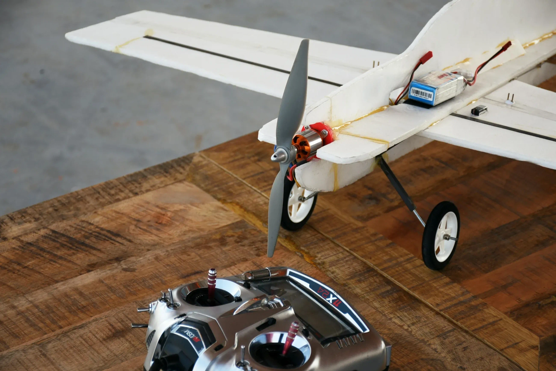
Why This Matters for RC Builders
Precision foam cutting allows hobbyists to create custom airfoils, fuselages, wingtips, and other lightweight components with accuracy and minimal mess. With the method described here, you can achieve clean, reliable cuts using affordable and accessible tools.
What Are the Next Steps?
While this calibration experiment helped determine the ideal power settings for various cutting lengths, the current bench setup isn't the most practical for real-world foam shaping. To make the process more efficient and ergonomic, the next step is to design a proper foam-cutting platform.
Some potential improvements include:
- Building a vertical cutting frame, where the hotwire is fixed vertically and the foam is moved across it
- Creating a movable bow-style cutter with adjustable tension and a handheld or guided cutting approach
- Adding a cutting fence or guide for straight lines and repeatable cuts
- Integrating rulers or positioning aids to precisely size wing profiles or fuselage sections
- Getting a fixed-voltage power adapter that matches the voltage and current requirements you’ve calibrated for (e.g., 12V/2A or 14V/1.8A), which eliminates the need for a bulky bench power supply
A well-constructed frame paired with a reliable power source will make clean, accurate cuts faster, safer, and more convenient—especially for repetitive or precision foam-cutting tasks in RC airplane builds.
Related Topics:
The tail section of an airplane plays a critical role in the stability, control, and performance of the aircraft. Whether you're building a foam RC model or designing a full-scale airplane, understanding tail configurations helps you make informed decisions about flight characteristics like yaw control, pitch stability, and aerodynamic efficiency

Dihedral wing design is a foundational element in aircraft stability engineering. By angling the wings upward, designers introduce a natural restoring force that improves roll stability and helps maintain level flight. This makes dihedral ideal for aircraft where ease of control and passive stability are important, such as gliders, UAVs, and training platforms

Wing design is a critical aspect of aerodynamics, influencing how an aircraft generates lift and remains airborne. Whether in birds, aircraft, or drones, the shape, size, and configuration of wings play a vital role in determining their efficiency and performance. This article explores the principles of lift force, how different wing designs impact flight, and key aerodynamic factors engineers consider when designing wings.

Aspect ratio is a fundamental design variable in aircraft engineering. High aspect ratios have aerodynamic efficiency and stable flight characteristics, while low aspect ratios enhance manoeuvrability, structural practicality, and internal space. Engineers must balance these tradeoffs based on the aircraft's intended mission, performance goals, and physical constraints

Flying is one of the most fascinating phenomena in nature and engineering. Whether it's birds soaring through the sky or an airplane cruising at 30,000 feet, the principles of flight remain the same. At the heart of flight physics are four fundamental forces that act on any flying object: lift, weight (gravity), thrust, and drag. Understanding how these forces interact is crucial to explaining how objects achieve and sustain flight.
Resistors are key in electronics, from LED circuits to advanced projects. This guide covers their function, types, identification, and a relatable analogy to simplify learning.
Or you can explore other categories
Electronics