The Breadboard: A Must-Have Tool for Every Electronics Enthusiast

Introduction
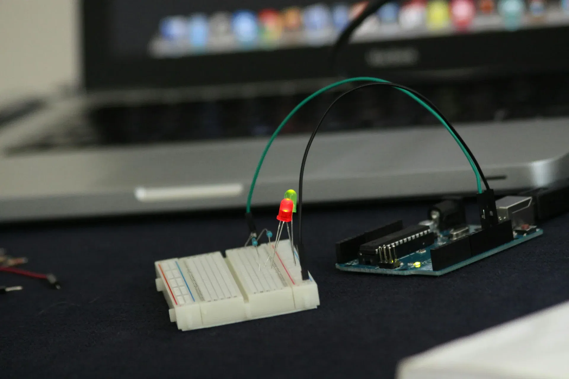
The breadboard is an essential tool for anyone interested in electronics, from beginners to experienced engineers. It provides a convenient and reusable platform for building and testing circuits without the need for soldering. This article explores what a breadboard is, why it is important, how it is constructed, and how to use it effectively in electronic projects.
Why Is the Breadboard Important?
Breadboards are invaluable for electronics enthusiasts and professionals alike because they:
- Enable rapid prototyping: Components can be quickly arranged and rearranged without permanent connections.
- Eliminate the need for soldering: This makes circuit assembly and modifications easier and safer, especially for beginners.
- Support learning and experimentation: Breadboards allow users to test and refine circuit designs before finalizing them on a printed circuit board (PCB).
- Are reusable and cost-effective: Unlike soldered circuits, breadboards can be used repeatedly for different projects.
How Is a Breadboard Constructed?
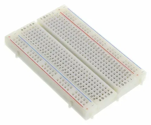
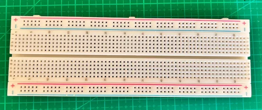
A breadboard consists of a plastic base with numerous small holes arranged in a grid pattern. Underneath the surface, metal strips run horizontally and vertically to create electrical connections. A typical breadboard has the following key sections:
- Power Rails: These are long rows running along the top and bottom, typically labeled with red (+) and blue (-) lines. They are used to distribute power throughout the circuit.
- Terminal Strips: These are the main working areas where components are inserted. Each vertical column (in the middle section) is internally connected, allowing components to be linked together easily.
- Middle Gap: A horizontal separation in the center accommodates integrated circuits (ICs), ensuring that each side remains electrically isolated.
Understanding the Breadboard Grid System
Breadboards have a grid system labeled with letters and numbers to help users identify specific rows and columns for component placement. The grid consists of:
- Rows labeled with numbers: These run horizontally and help in locating specific component connections.
- Columns labeled with letters: These run vertically and assist in identifying precise insertion points.
- Each numbered row is internally connected: Within a given section, all five holes in a numbered row (A-E on one side and F-J on the other) are electrically linked.
- The central gap ensures that the two sides of the breadboard remain isolated unless explicitly connected.
This labeling system makes it easier to follow circuit diagrams and systematically place components without confusion.
Different Sizes of Breadboards
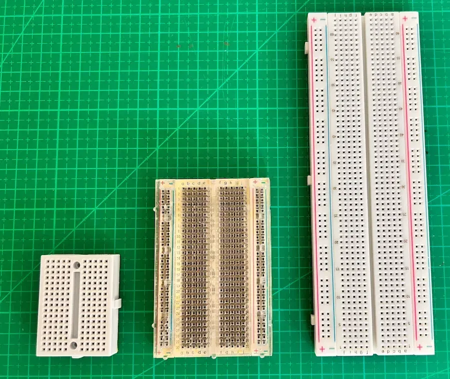
Breadboards come in various sizes to accommodate different project needs:
- Mini Breadboards: These compact breadboards typically have around 170 tie points and are ideal for small projects and simple circuits.
- Half-Size Breadboards: With approximately 400-450 tie points, these are useful for moderately complex circuits while still being compact.
- Full-Size Breadboards: These larger boards have around 830-900 tie points and provide ample space for complex circuits and prototyping needs.
- Extended Breadboards: Some breadboards can be connected together to create an even larger working area, allowing for extensive prototyping setups.
Choosing the right size depends on the complexity of your project and the number of components you need to connect.
How to Use a Breadboard
Using a breadboard effectively requires understanding its internal structure and following a few simple steps:
- Plan Your Circuit: Sketch your circuit diagram before placing components to ensure proper connections.
- Insert Components: Place resistors, capacitors, transistors, ICs, and other components into the holes of the terminal strip.
- Connect with Jumper Wires: Use jumper wires to establish electrical connections between different components and power rails.
- Supply Power: Connect a power source such as a battery pack or a regulated power supply to the breadboard’s power rails.
- Test and Debug: Use a multimeter to check for proper voltage and continuity. If the circuit does not function as expected, rearrange components as needed.
Types of Wires Used
When working with a breadboard, the following types of wires are commonly used:
- Jumper Wires: These are pre-cut and stripped wires with male or female ends, ideal for quick and easy connections.
- Solid Core Wires: These provide stable and firm connections, making them great for use on breadboards.
- Stranded Wires: Although flexible, they can be difficult to insert into breadboard holes and are generally not recommended unless tinned beforehand.
Best Practices for Clean and Organized Breadboarding
- Use color-coded wires: Assign colors for different connections (e.g., red for power, black for ground, blue for signals) to avoid confusion.
- Avoid long wires over components: Long wires that cross over components can make troubleshooting difficult. Keep wires short and direct.
- Use short wires around components: Arrange wires neatly to go around components instead of over them, ensuring a clear and organized setup.
Common Mistakes to Avoid
- Getting power and ground mixed up: Always double-check connections to ensure that power and ground are correctly assigned. Reversing these connections can damage components.
- Power rails may not be fully connected: In some breadboards, the power rails are split in the middle, meaning they are not electrically connected throughout the entire length. Always check continuity with a multimeter or bridge the gap with a jumper wire.
- Not pushing leads and wires in all the way: Ensure that component leads and wires are firmly inserted into the breadboard holes; loose connections can cause intermittent issues and make debugging difficult.
- Crossing power rails incorrectly: Always verify that the positive and negative rails are correctly connected to prevent short circuits.
- Placing components in the wrong holes: Double-check component placement to ensure proper connectivity.
- Overloading connections: Avoid inserting multiple wires into a single hole, as this can weaken connections.
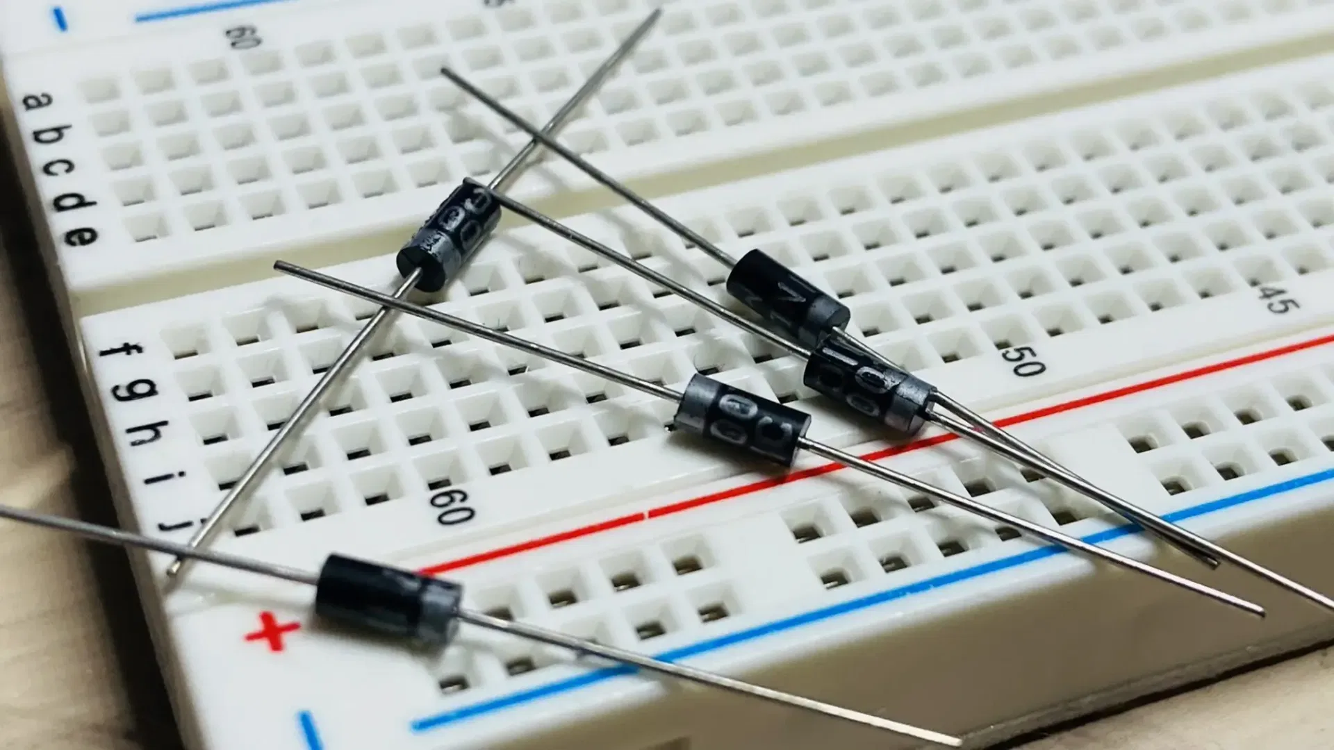
- Putting components in backwards: Certain components like diodes, electrolytic capacitors, and transistors have polarity and must be inserted in the correct orientation. Reversing them can lead to circuit malfunctions or damage.
- Not trimming long leads of resistors or capacitors: Components come with long leads, and placing them on a breadboard without trimming might cause their leads to touch, leading to short circuits. Always trim excess lead length before inserting them into the breadboard.
- Using resistors or capacitors with the wrong value: Verify the values of components before inserting them into the circuit, as an incorrect value can lead to improper circuit operation.
- Not verifying continuity of connections: Use a multimeter to check for connectivity and ensure no broken connections in the circuit.
- Using inappropriate jumper wires: Thick wires may not fit properly in breadboard holes, while overly thin wires may not establish reliable connections.
- Not using color coding for wires: Using the same color for all connections can lead to confusion when debugging. Use different colors for power, ground, and signal connections.
- Relying on the breadboard for permanent use: Breadboards are for prototyping only. Final designs should be transferred to a PCB for more stable connections.
- Failing to disconnect power when modifying circuits: Always disconnect the power source before making changes to avoid short circuits or component damage.
- Using dirty or oxidized component leads: Ensure that component leads are clean before inserting them into the breadboard for proper electrical contact.
- Ignoring heat dissipation for components: Components like transistors and voltage regulators can become hot. Use heat sinks if necessary.
- Not securing components properly: If components are loosely placed in the breadboard, they may cause unstable connections and signal interruptions.
- Using a damaged breadboard: Over time, breadboards can wear out. If you experience persistent connection issues, consider using a new one.
Conclusion
The breadboard is an indispensable tool for anyone working with electronics. It simplifies circuit prototyping, encourages learning through hands-on experimentation, and allows for easy modifications. Whether you are a student, hobbyist, or professional engineer, mastering the use of a breadboard will greatly enhance your ability to design and test electronic circuits efficiently.
Related Topics:
Discover the fundamentals of diodes, their types, functions, and applications in electronics. Learn how diodes are used in power rectification, voltage regulation, signal processing, and more.
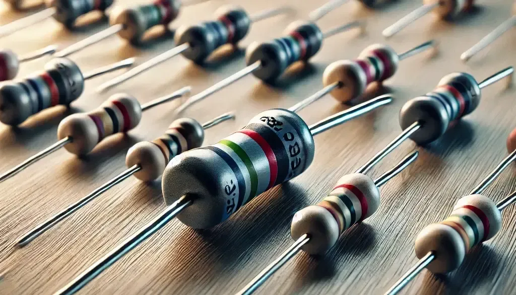
Resistors are key in electronics, from LED circuits to advanced projects. This guide covers their function, types, identification, and a relatable analogy to simplify learning.
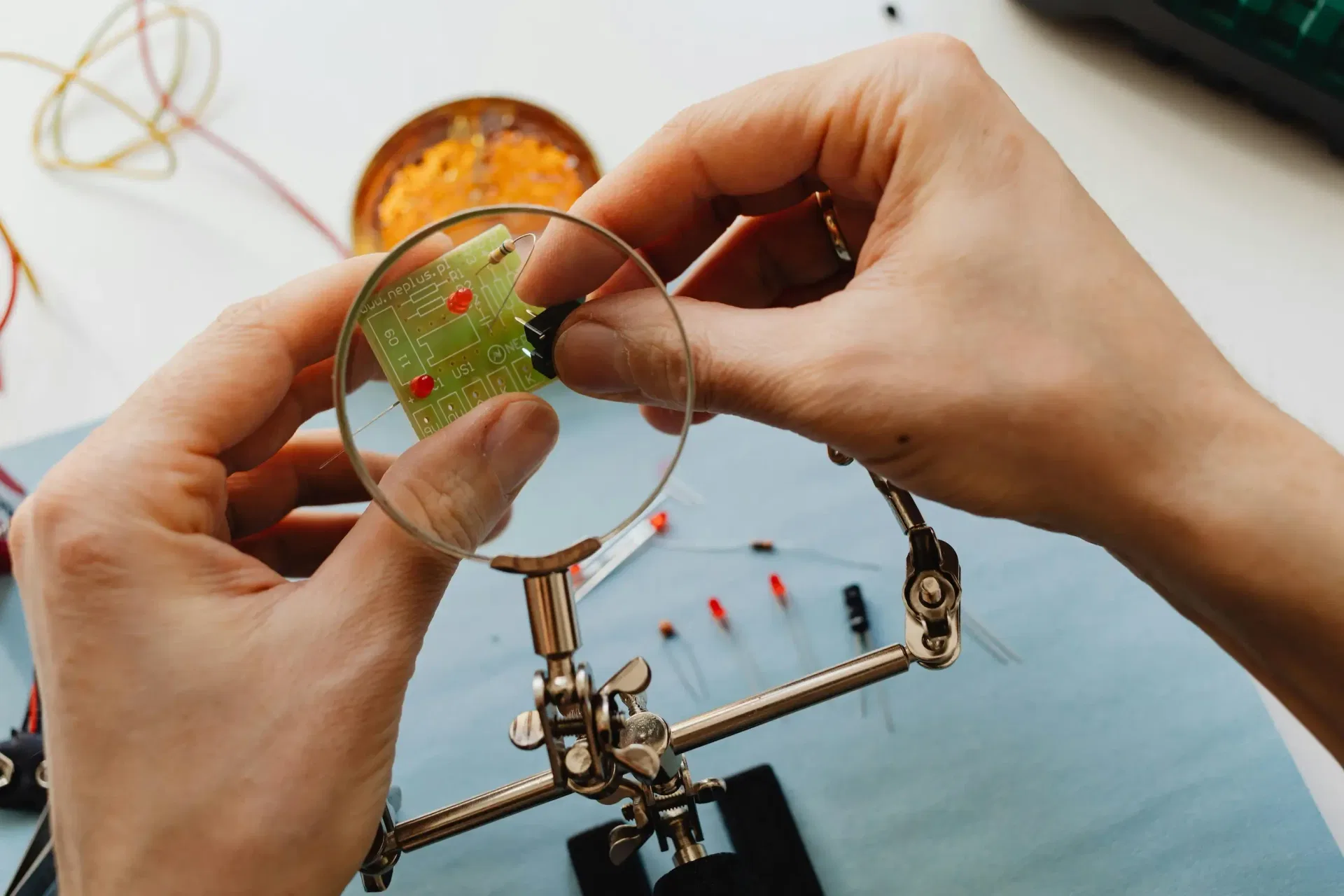
This article explores the fundamental aspects of indicator LEDs, including their pin configuration, identification of anode and cathode, correct circuit connection, current protection methods, and more
Or you can explore other categories
Electronics