Using Diodes as Rectifiers

Using Diodes as Rectifiers: Half-Wave and Full-Wave Rectification Explained
Introduction
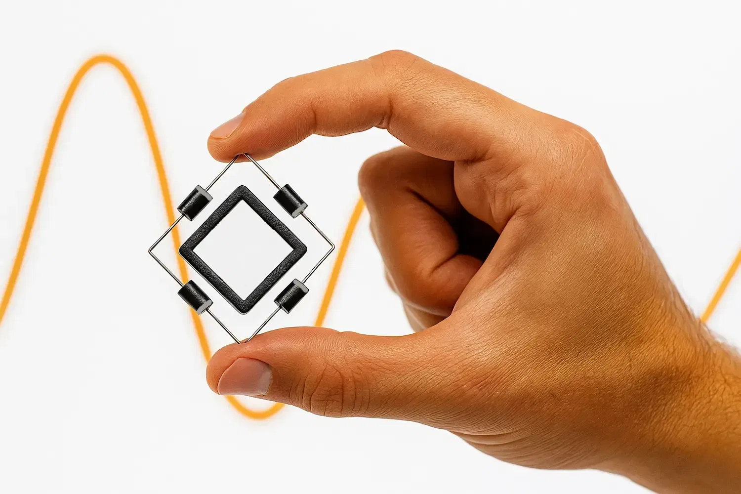
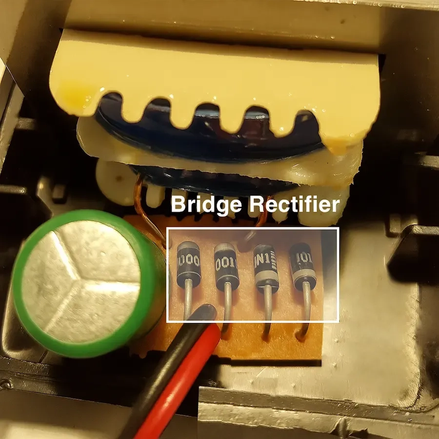
Have you ever cracked open an old DC adapter out of curiosity? If you did, you probably noticed four small black diodes arranged neatly in a square or diamond shape. That formation is no accident — it’s called a full-wave bridge rectifier, and it’s the unsung hero responsible for turning your wall's AC power into the smooth DC current your devices need.
Rectifiers are essential in nearly every electronic device. Without them, your Arduino, laptop charger, or even your TV wouldn't get the kind of power they require. In this article, we’ll explore how diodes are used to rectify AC into DC, starting with the simple half-wave rectifier and then diving into the more powerful full-wave bridge configuration. Whether you're building your own power supply or just want to understand what’s happening inside that adapter, this guide will make it clear.
What Is a Rectifier?
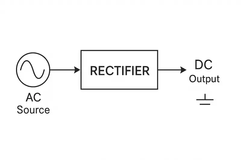
A rectifier is an electronic circuit that converts alternating current (AC) — which constantly changes direction — into direct current (DC), which flows in only one direction. This process is called rectification, and the core component that makes it possible is the diode.
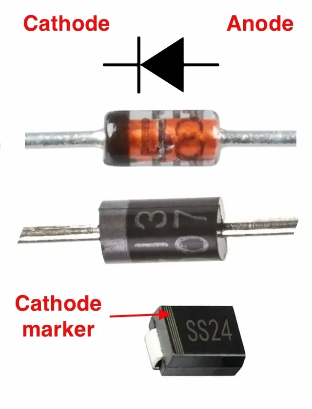
A diode acts like a one-way valve for electric current. It allows current to flow in one direction (forward-biased) and blocks it in the other (reverse-biased). This property is what enables the conversion of AC to DC.
Are All Diodes the Same?
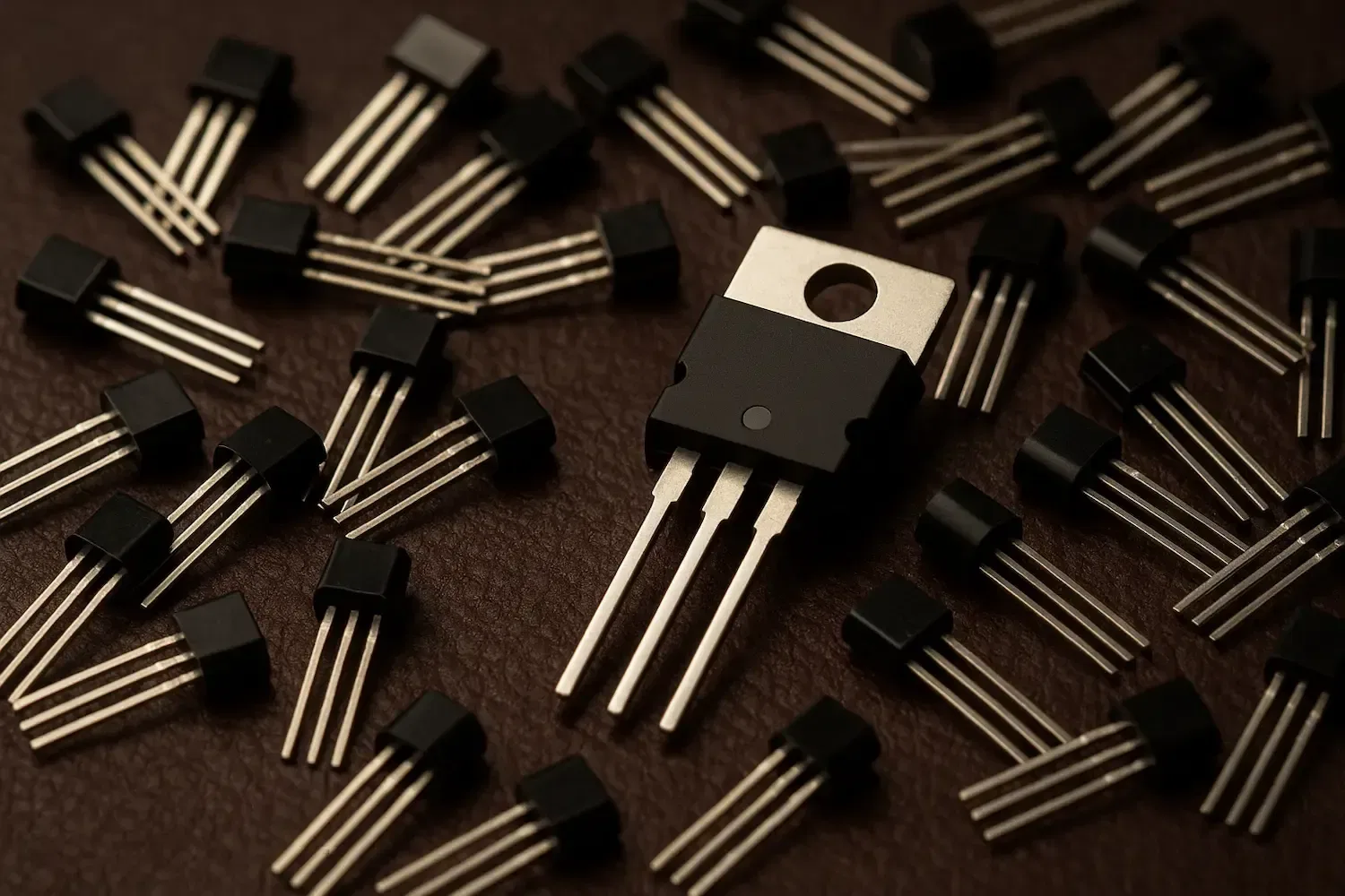
While all diodes share the basic one-way behavior, they come in different types optimized for specific uses. A common source of confusion is between rectifier diodes and Light Emitting Diodes (LEDs).
- Rectifier diodes are designed to handle higher currents and voltages, making them ideal for power conversion.
- LEDs, on the other hand, are built to emit light and are sensitive to high current — they typically operate safely below 30 mA.
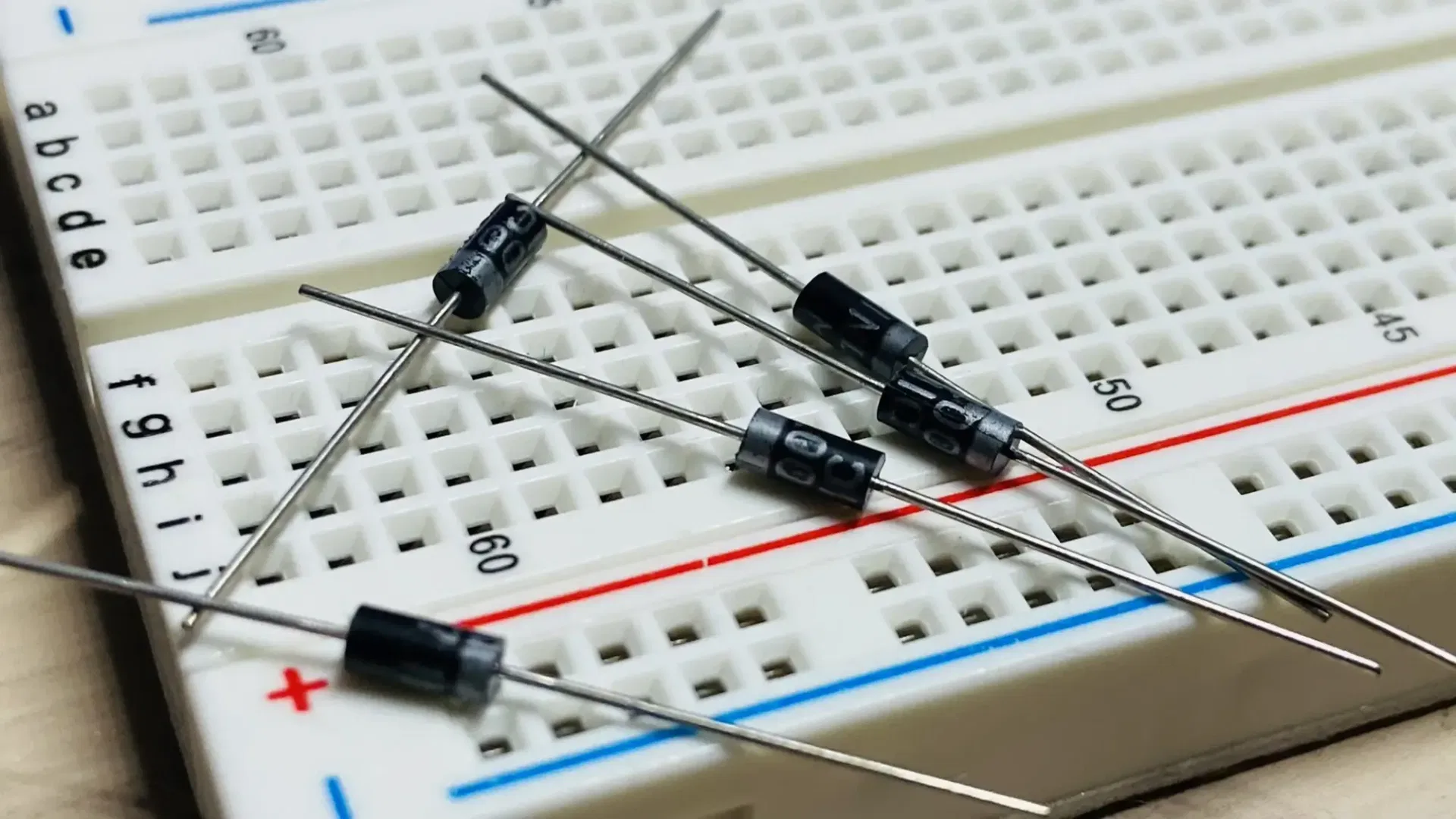
If you open a typical 12V DC adapter, you'll often see four black cylindrical diodes arranged in a square — forming a full-wave bridge rectifier. These are likely:
- 1N5408 diodes, rated for up to 3 amps and 1000 volts, or
- 6A10 diodes, which handle up to 6 amps and are used in higher-wattage adapters.
This illustrates the big difference between signal diodes, LEDs, and power-handling rectifiers — using the right type matters.
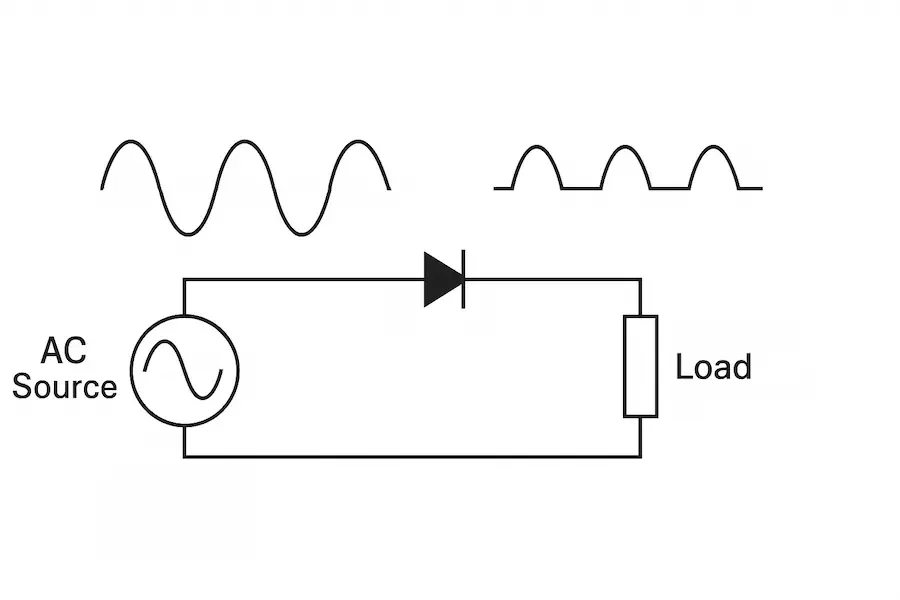
Half-Wave Rectification
How It Works
In a half-wave rectifier, only one diode is used. During the positive half of the AC cycle, the diode is forward-biased and allows current to pass to the load. During the negative half, the diode blocks the current, resulting in pulsed DC output.
Output Waveform
The output consists of only the positive halves of the input sine wave. The negative halves are completely cut off, so the result is a series of pulses separated by zero-voltage gaps.
Pros and Cons
Pros:
- Very simple to build
- Requires only one diode
Cons:
- Very inefficient (uses only half of the input waveform)
- High ripple (not smooth)
- Not suitable for high-power applications
Practical Use Cases
- Signal demodulation
- Low-power circuits where simplicity is more important than efficiency
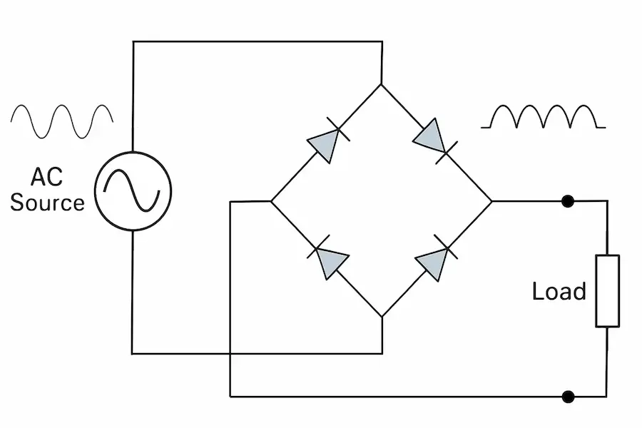
Full-Wave Rectification Using a Bridge Rectifier
How It Works
The bridge rectifier uses four diodes arranged in a square or diamond pattern. During each half of the AC cycle, two of the diodes conduct and direct current through the load in the same direction.
Output Waveform
Both the positive and negative halves of the AC input are utilised, producing a waveform that pulses twice as often as that of a half-wave rectifier. This results in smoother DC output with less ripple.
Pros and Cons
Pros:
- Uses the full AC waveform
- No need for a centre-tapped transformer
- Compact and widely used in DC adapters and power supplies
Cons:
- Two diodes conduct at once, causing a small voltage drop (about 1.4V total)
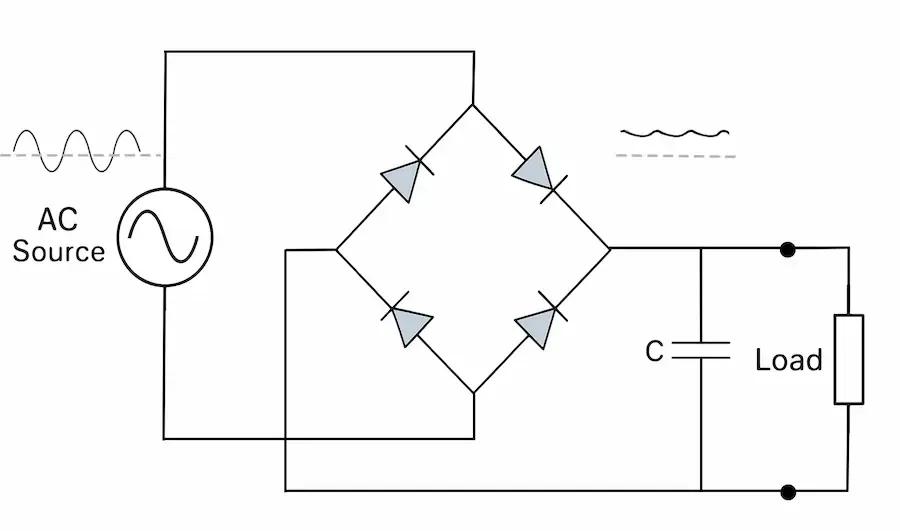
Filtering the Output
Rectifiers alone produce pulsed DC, which isn't ideal for sensitive electronics. To smooth the output, a filter capacitor is added. It charges when voltage rises and discharges slowly when it falls, filling in the gaps between pulses.
Extra Smoothing
For even better performance, circuits may include:
- Capacitor + resistor (RC) filters
- Inductors
- Voltage regulators (like 7805, LM317)
Compensating for Diode Voltage Drop
In a bridge rectifier, the 1.4V drop (0.7V per diode) can reduce the output voltage below the desired level. Fortunately, there are two easy ways to compensate:
- Increase the AC secondary voltage slightly — typically by about 1.4V. This ensures that, after rectification, the output voltage reaches your target.
- Add a voltage regulator after the rectifier and filter stages. Regulators like the 7805 (5V fixed) or LM317(adjustable) help stabilize the voltage and eliminate minor fluctuations.
These techniques are often used together in power supplies to maintain consistent DC output.
Applications of Rectifiers
Rectifiers are used in countless electronic devices, including:
- Phone and laptop chargers
- Power supplies for microcontrollers (e.g., Arduino)
- Battery charging circuits
- Audio amplifiers
- Industrial control equipment
Conclusion
Diodes might be small, but their role in converting AC to DC is enormous. Whether it’s a single diode in a basic half-wave rectifier or a four-diode bridge powering your favorite gadget, rectifiers are at the core of modern electronics. Understanding how they work opens the door to designing your own power supplies and deepening your knowledge of electronic systems.
Related Topics:

Understand Electronic Speed Controllers (ESC) for RC planes. Learn how ESC works, choosing the right size, cooling tips, and what happens if misused. Perfect guide for beginners and hobbyists
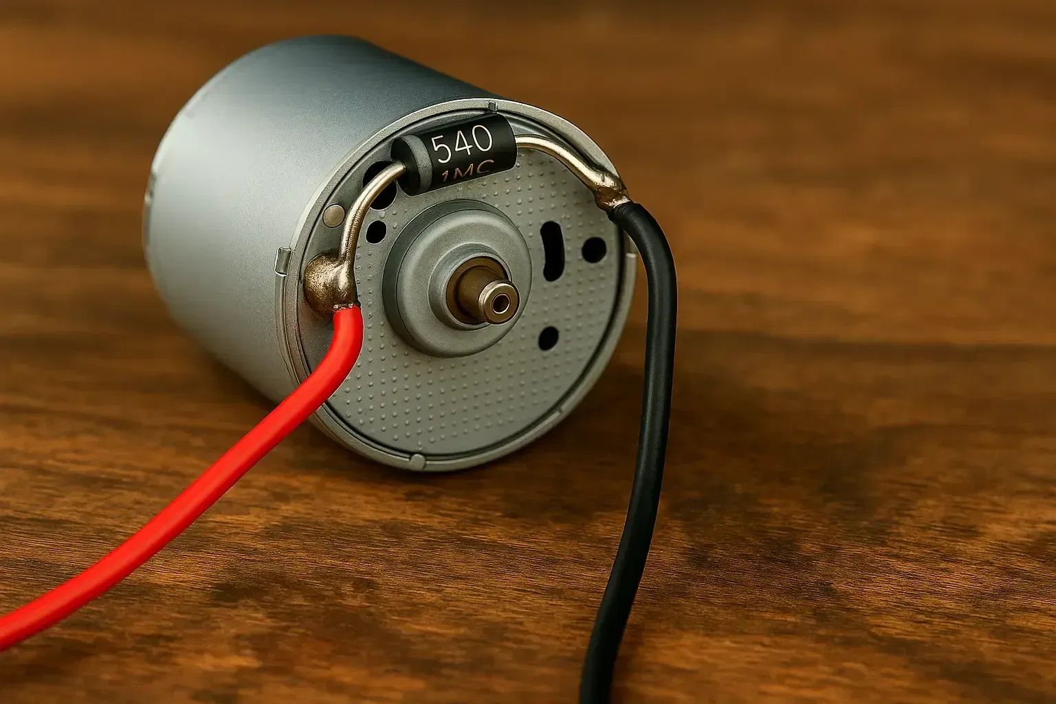
Discover what flyback diodes are, how they work, and why they are crucial for protecting your circuits from voltage spikes caused by inductive loads like motors and relays.
Learn how to use a MOSFET as a simple electronic speed controller (ESC) for mini brushed DC motors. This beginner-friendly guide explains the circuit design, control method, and tips for safe operation

Learn how Pulse Width Modulation (PWM) works and how it's used to control LED brightness, motor speed, and servos in electronics and RC projects. Simple explanations with real-world examples.
Discover the fundamentals of diodes, their types, functions, and applications in electronics. Learn how diodes are used in power rectification, voltage regulation, signal processing, and more.

This article explores the fundamental aspects of indicator LEDs, including their pin configuration, identification of anode and cathode, correct circuit connection, current protection methods, and more
Or you can explore other categories

Electronics