What Is PWM?


What Is PWM? A Simple Way to Control Power in Electronics
Have you ever seen a light smoothly dim or heard a fan gradually speed up? Behind these effects is a clever technique used in electronics called PWM, or Pulse Width Modulation.
This article explains PWM in a simple way, using real-life examples and analogies that anyone can understand — even if you’re new to electronics.
1. What Is PWM?
PWM stands for Pulse Width Modulation — a technique used to control the amount of power delivered to a device without changing the actual voltage.
Instead of turning something ON at half power, PWM turns it fully ON and OFF very quickly — thousands of times per second. By changing how long the signal stays ON during each cycle, we can control how much average power the device receives.
2. A Simple Analogy: Manually Controlling a Light Switch
Let’s say a person manually turns a room light ON and OFF every day.
- He turns it ON for 6 hours, then OFF for 18 hours, and repeats this pattern forever.
- Over a 24-hour day, the light is ON for only 6 out of 24 hours, or 25% of the time.
- Even though the light is either fully ON or fully OFF, the average power consumption is 25% compared to leaving it on all day.
If he changes the pattern to 12 hours ON, 12 hours OFF, that’s a 50% duty cycle, and the average power is now 50%.
This is how PWM works — but instead of switching every 24 hours, it switches thousands of times per second, so everything looks smooth and continuous.

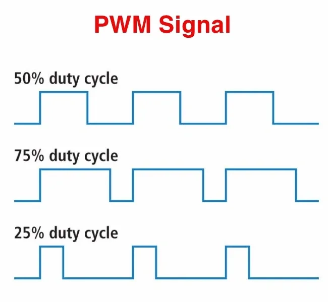
3. What Is Duty Cycle?
The duty cycle is the percentage of time that the power is ON during each full cycle.
- 100% duty cycle → always ON
- 50% duty cycle → ON half the time
- 25% duty cycle → ON one-quarter of the time
- 0% duty cycle → always OFF
This percentage controls how much power is delivered on average.
For example, if an LED receives PWM with:
- 100% duty cycle → full brightness
- 50% duty cycle → half brightness
- 10% duty cycle → very dim
4. Where Is PWM Used?
PWM is used in many everyday devices and electronic applications:
- LED dimming – Adjusting brightness smoothly
- Fan control – Varying motor speeds in computers and appliances
- Motor control – Running motors at different speeds in toys, robots, and tools
- Sound generation – Creating tones in buzzers and audio circuits
- RC models – Controlling servos and throttle in RC airplanes and drones
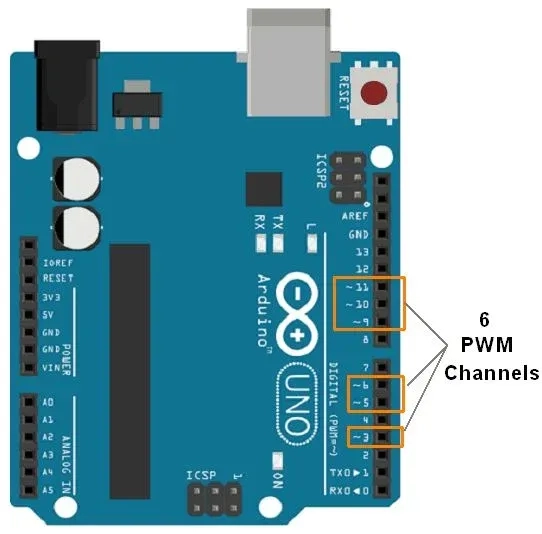
PWM is especially popular in microcontroller projects like those using Arduino. For instance, using the Arduino function analogWrite(pin, value) lets you control brightness or motor speed easily using PWM on special pins (such as ~3, ~5, ~6).
5. Why Not Just Lower the Voltage?
You might wonder — why not simply reduce the voltage to dim a light or slow a motor?
Here’s why that doesn’t always work:
Imagine you want to dim an LED to just 10% brightness. You might try lowering the voltage from 5V to 0.5V — but it won’t light up. Most LEDs require at least 0.7V just to turn ON. Below that, they remain completely OFF.
With PWM, we keep the voltage at 5V, but change the duty cycle to 10%. This way:
- The LED still gets enough voltage to light up.
- But since it’s ON only 10% of the time, it appears dim.
- The average power it receives is just 10%.
PWM provides precision, efficiency, and compatibility with digital systems — without wasting energy as heat.
6. PWM and Servo Motors: Controlling Angles with Precision
PWM also plays a key role in controlling servo motors, which are widely used in robotics, RC airplanes, and automation systems.
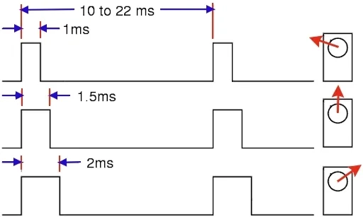
A typical servo motor is designed to rotate to a specific angle between 0 and 180 degrees. But it doesn’t respond to ordinary voltage — it expects a PWM signal with precise timing.
- The PWM signal repeats every 20 milliseconds.
- The pulse width (how long the signal stays ON) tells the servo where to move:
- A 1 millisecond pulse corresponds to 0 degrees.
- A 1.5 millisecond pulse moves it to 90 degrees.
- A 2 millisecond pulse moves it to 180 degrees.
This allows fine control of the servo’s position.
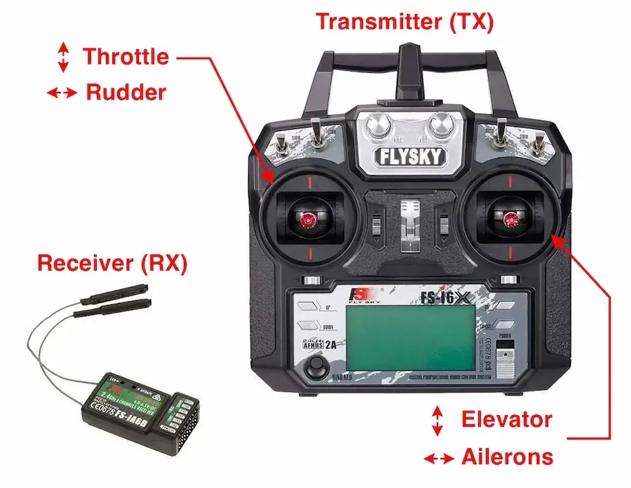
How RC Transmitters Generate PWM
Inside a radio transmitter like FlySky, each stick is connected to a potentiometer, which acts like a voltage divider.
- Moving the stick changes the resistance, which adjusts the voltage level.
- That voltage is read by the transmitter’s electronics and mapped to a PWM pulse width.
- The transmitter sends that PWM signal wirelessly to the receiver.
- The receiver outputs the correct PWM signal to the servo, which rotates to the corresponding angle.
For example, moving the stick fully left might generate a 1 ms pulse (0°), centered might give 1.5 ms (90°), and fully right gives 2 ms (180°).
This entire process allows precise control of servo-based systems — from airplane rudders to robot arms.
7. Final Thoughts
PWM might sound technical, but it's a simple and powerful method for controlling power, brightness, speed, and position. By turning a signal ON and OFF rapidly and adjusting the ON-time (duty cycle), PWM allows efficient and precise control in everything from small LED circuits to complex RC systems.
Whether you're dimming lights, adjusting motor speeds, or commanding servo angles — PWM is quietly working in the background, making it all possible.
Related Topics:
Discover the fundamentals of diodes, their types, functions, and applications in electronics. Learn how diodes are used in power rectification, voltage regulation, signal processing, and more.
Resistors are key in electronics, from LED circuits to advanced projects. This guide covers their function, types, identification, and a relatable analogy to simplify learning.

This article explores the fundamental aspects of indicator LEDs, including their pin configuration, identification of anode and cathode, correct circuit connection, current protection methods, and more
Or you can explore other categories

Electronics