Voltage Divider Circuits

Understanding Voltage Divider Circuits in Electronics
Introduction
In electronics, we often need to obtain a specific lower voltage from a higher one. One of the simplest ways to do this is by using a voltage divider circuit. This basic yet powerful concept is widely used in both analog and digital electronics.
What is a Voltage Divider?
A voltage divider is a simple circuit made of two resistors connected in series. Its main purpose is to divide the input voltage into a lower output voltage that can be used by other parts of the circuit.
How Does It Work? (Basic Principle)
When two resistors are connected in series across a voltage source, the current passing through both resistors is the same. However, the voltage across each resistor depends on its resistance value according to Ohm's Law.
Voltage Divider Formula Explained
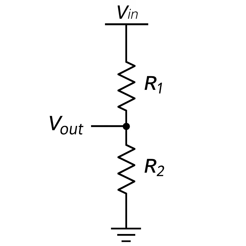
For two resistors R1 and R2 connected in series across an input voltage Vin, the output voltage Vout is taken from the point between R1 and R2.
The formula for Vout is:
This equation shows that the output voltage depends on the ratio between the two resistor values.
Example Circuit and Calculation
Circuit:
- Vin=12V
- R1=4kΩ
- R2=2kΩ
Calculation:
This means the output voltage across R2 will be 4 volts.
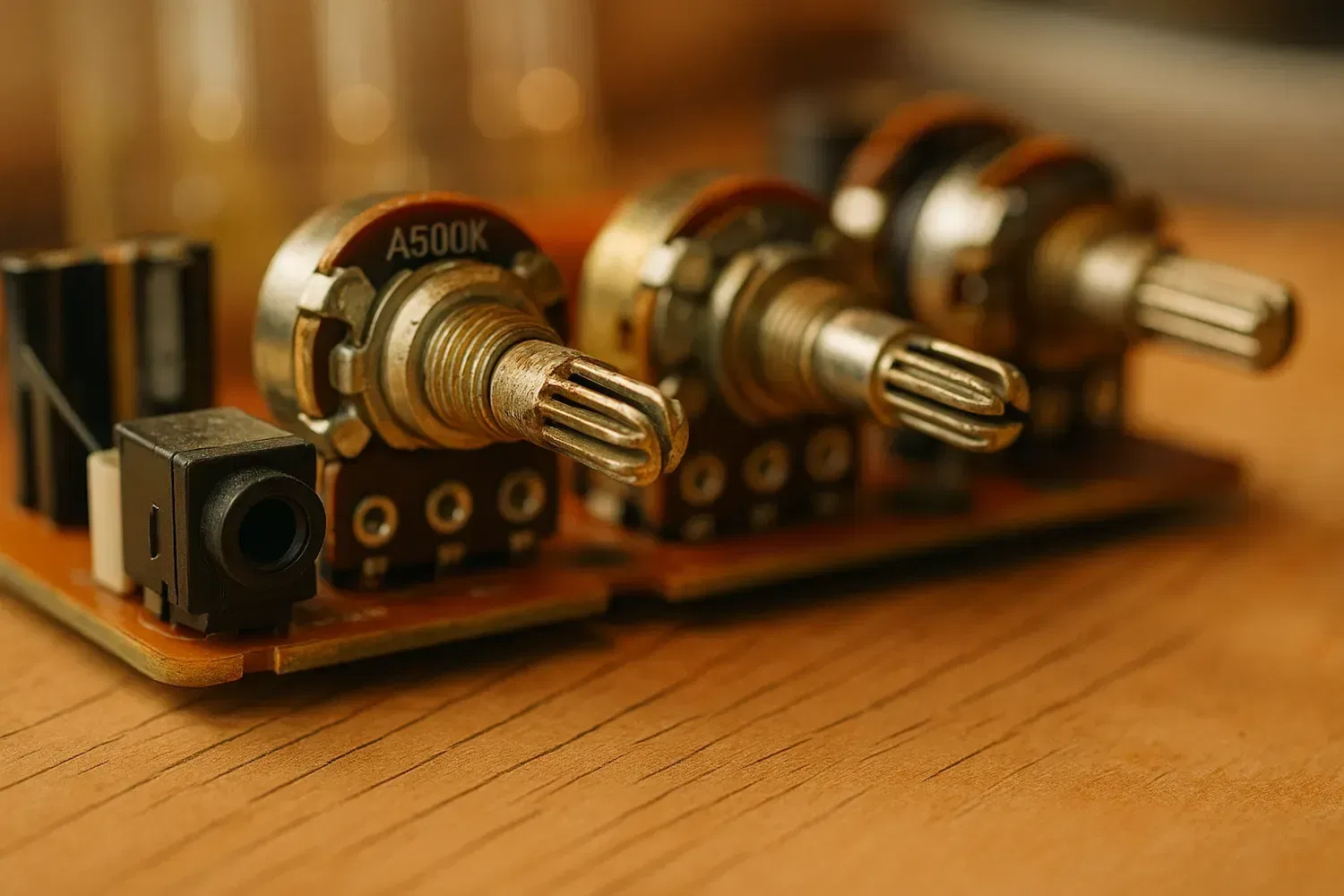
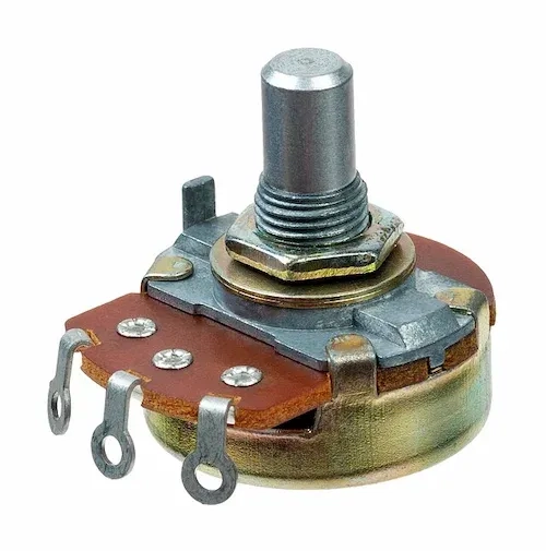
Using a Potentiometer as a Voltage Divider
A potentiometer is a three-terminal variable resistor that is perfectly suited for creating adjustable voltage dividers. Inside the potentiometer, a resistive element is connected between the two outer terminals, while the middle terminal (called the wiper) can slide along the resistive track.
When you connect the two outer terminals to a voltage source and take the output from the wiper, the potentiometer acts exactly like a variable voltage divider. By rotating the knob, you adjust the position of the wiper, changing the resistance ratio between the two sides, and therefore varying the output voltage.
This is a very common technique used in:
- Volume control in audio circuits.
- Adjusting contrast or brightness in displays.
- Setting reference voltages in circuits.
Important Tip:
When using a potentiometer as a voltage divider, always ensure that the load connected to the wiper does not draw significant current, or the voltage might become unstable or inaccurate.
Applications of Voltage Dividers
Voltage dividers are widely used in many electronic applications, such as:
- Creating reference voltages.
- Scaling down voltages for analog-to-digital converters (ADC).
- Adjusting signal levels between circuits.
- Voltage sensing circuits.
Important Considerations and Limitations
- Load Effect: The voltage divider only provides the expected output voltage if the load connected to Vout does not draw significant current. Adding a heavy load will change the output voltage.
- Power Dissipation: Ensure that resistors can handle the power they dissipate without overheating.
- Not for Power Supply: Voltage dividers are not suitable for delivering power to loads, only for signal-level or sensing purposes.
Conclusion
The voltage divider is a fundamental building block in electronics. Understanding how it works allows you to design circuits that need specific voltages from a fixed source. However, always consider the limitations and avoid using it for powering devices directly.
Related Topics:
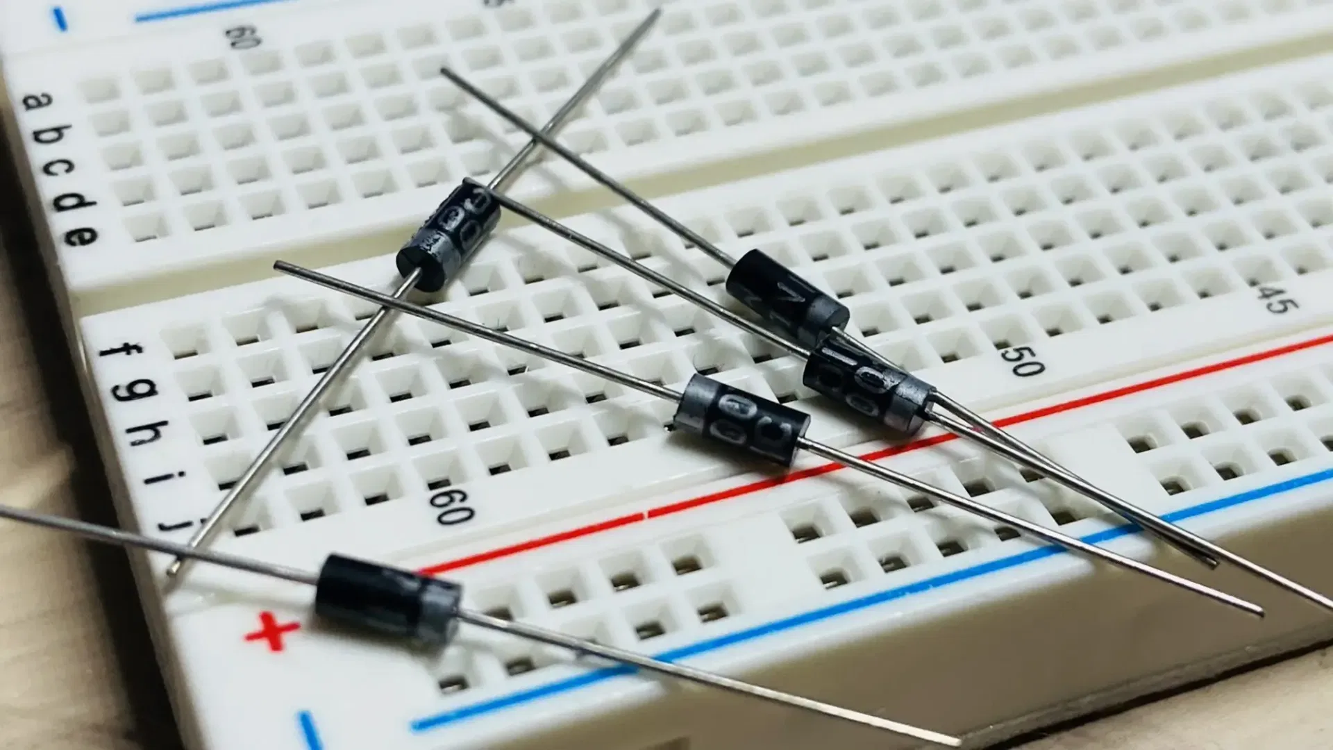
Discover the fundamentals of diodes, their types, functions, and applications in electronics. Learn how diodes are used in power rectification, voltage regulation, signal processing, and more.
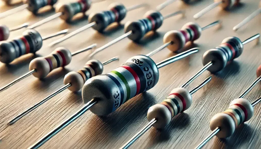
Resistors are key in electronics, from LED circuits to advanced projects. This guide covers their function, types, identification, and a relatable analogy to simplify learning.

This article explores the fundamental aspects of indicator LEDs, including their pin configuration, identification of anode and cathode, correct circuit connection, current protection methods, and more
Or you can explore other categories
Electronics