Non-Inverting Operational Amplifier

Understanding the Non-Inverting Operational Amplifier: Theory, Design, and Applications
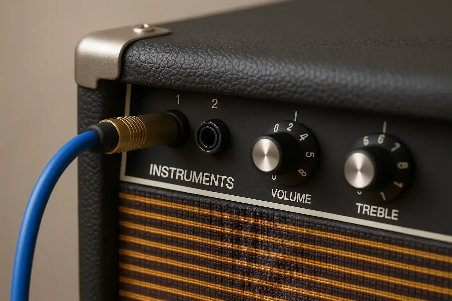
Operational amplifiers (op-amps) are fundamental building blocks in analog electronics, and one of their most commonly used configurations is the non-inverting amplifier. In this article, we'll explore how this configuration works, its voltage gain formula, how to build it, and some real-world applications.
1. What is a Non-Inverting Amplifier?
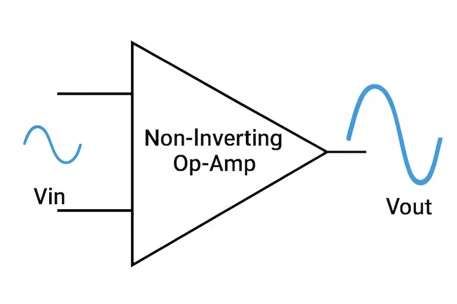
A non-inverting amplifier is a circuit configuration where the input signal is applied to the non-inverting (+) input of the op-amp. This results in an output signal that is in phase with the input and amplified by a predictable gain.
Unlike the inverting amplifier, the non-inverting configuration does not flip the polarity of the input signal. This is important when you want to maintain signal phase while amplifying voltage.
2. Circuit Configuration
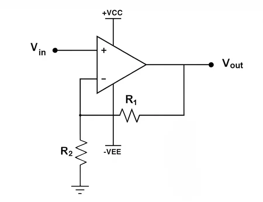
The basic non-inverting amplifier consists of:
- An op-amp IC (e.g., LM741, TL081, LM358)
- Two resistors: R1 (connected from output to inverting input) and R2 (connected from inverting input to ground)
- The input signal connected to the non-inverting input
The gain is controlled by the ratio of R1 to R2, and the output is taken directly from the op-amp’s output pin.
3. Voltage Gain Formula
The voltage gain (Av) of a non-inverting amplifier is determined by the feedback resistor network:
- R1 is the resistor between output and the inverting input
- R2 is the resistor from inverting input to ground
This formula shows that the gain is always greater than or equal to 1.
Example:
If R1 = 10kΩ and R2 = 2kΩ:
So, an input of 1V would result in an output of 6V.
This means the output voltage will be 6 times the input voltage (as long as the op-amp is not saturating).
Make sure to:
- Connect power pins correctly (Vcc and Vee or GND)
- Add a 0.1µF decoupling capacitor between Vcc and ground
- Use a breadboard or PCB with good layout to minimise noise
4. Practical Considerations
- Power Supply: Most op-amps need dual supplies (e.g., ±12V), but some like the LM358 work with a single supply (e.g., 0–5V).
- Input Bias Current: Always ensure that a DC path to ground exists for the inputs.
- Bandwidth and Slew Rate: At high gains or high frequencies, op-amp limitations can affect performance.
- Stability: Use bypass capacitors near the power pins to reduce noise and oscillations.
5. Applications of Non-Inverting Amplifiers
This configuration is widely used in:
- Audio signal amplification: Boosting microphone or line-level signals.
- Buffer stages: Due to high input impedance, non-inverting amplifiers are ideal as voltage followers (unity gain).
- Sensor signal conditioning: Amplifying voltage output from temperature, light, or pressure sensors.
- Data acquisition: Used before ADCs to scale signals to the required range.
6. Single Supply vs Dual Supply Operation
Op-amps can be powered using either a dual supply (e.g., ±12V) or a single supply (e.g., 0–5V), but the behaviour of the amplifier changes depending on the choice. This has important implications for the input range, output swing, and biasing of the circuit.
Dual Supply (±V)
- In dual supply configurations, the op-amp can handle both positive and negative input voltages.
- The output can swing above and below 0V, centred around 0V.
- This is ideal for AC signals, as the op-amp can amplify the entire waveform without clipping.
- No need to bias the input signal.
Single Supply (0 to +V)
- The op-amp operates only in the positive voltage range, typically from 0V up to just below the supply voltage(e.g., 0–5V).
- The output cannot go below 0V, and many op-amps can’t even reach all the way to 0V or Vcc due to internal limitations (this is known as “output swing limitation”).
Implications of Single Supply:
- Clipping Risk: If the input signal goes below 0V or the amplified signal attempts to go negative, the output will be clipped at or near 0V, distorting the waveform.
- Re-Biasing Required: To amplify AC signals with a single supply, the input must be DC-biased to mid-supply(e.g., 2.5V for a 5V system). This ensures the signal stays within the input and output range of the op-amp.
- Coupling Capacitors: Capacitors are typically used at the input and output to remove the DC bias, allowing the circuit to handle pure AC signals externally.
Example:
If you're amplifying a 1V peak-to-peak AC signal centred at 0V using a single 0–5V supply, you must shift the input signal so it's centred at 2.5V instead of 0V. Otherwise, the negative half of the waveform will be lost (clipped).
Conclusion
The non-inverting amplifier is a simple yet powerful op-amp configuration. It allows you to amplify a signal without inverting its phase, making it ideal for signal processing, instrumentation, and audio circuits. By understanding its design and limitations, you can effectively use it in many analog applications.
Related Topics:
Learn how diodes are used as rectifiers in electronics. Understand half-wave and full-wave rectification with real examples and practical insights for beginners and hobbyists

Discover how piezo buzzers work and how to use them in your electronics projects. This guide explains their function, wiring, and applications as sound emitters and sensors.
Learn what coupling capacitors are, why they're essential in electronic circuits, how they block DC while passing AC signals, and key considerations when using them in your designs
Learn how to use a MOSFET as a simple electronic speed controller (ESC) for mini brushed DC motors. This beginner-friendly guide explains the circuit design, control method, and tips for safe operation

Discover how 7-segment displays work, their internal structure, types (common anode vs cathode), and how to use them in Arduino projects. Perfect for beginners and electronics enthusiasts.
Learn about transistors, their types, functions, and applications in modern electronics. Discover how BJTs, FETs, MOSFETs, and more are used in amplification, switching, and power control.
Or you can explore other categories
Electronics