Non-Inverting Amplifier as a Buffer


Using a Non-Inverting Amplifier as a Buffer
In many electronic circuits, we often face the challenge of transferring a signal from one stage to another without distortion or signal loss. This is where buffers come into play. Buffers are essential components that isolate different parts of a circuit while preserving the signal's integrity. One of the most common and effective ways to implement a buffer is by using a non-inverting amplifier configured as a voltage follower.
What Is a Non-Inverting Amplifier?
A non-inverting amplifier is a basic operational amplifier (op-amp) configuration where the input signal is applied to the non-inverting terminal (marked +), and the output is fed back to the inverting terminal (marked –) through a pair of resistors. This feedback arrangement controls the gain of the amplifier.
The voltage gain Av of a non-inverting amplifier is given by the formula:
Where:
- Rf is the feedback resistor,
- Rin is the resistor connected between the inverting input and ground.
This configuration provides a high input impedance and low output impedance, making it ideal for many applications.

Turning It into a Buffer (Voltage Follower)
To use a non-inverting amplifier as a buffer, we simplify the configuration to achieve unity gain—that is, the output voltage exactly follows the input voltage:
This is done by:
- Removing both Rf and Rin,
- Connecting the output directly to the inverting input.
This setup is called a voltage follower. The op-amp still maintains high input impedance and low output impedance, but it doesn’t amplify the signal—it simply copies it.

Why Use a Buffer?
Buffers are incredibly useful in electronics for several reasons:
1. Prevent Loading Effects
Imagine a sensor with a high internal resistance connected directly to an analog-to-digital converter (ADC) with a low input impedance. The sensor may not be able to supply the required current, leading to inaccurate readings. A buffer in between solves this issue by drawing virtually no current from the sensor.
2. Isolate Circuit Stages
When connecting different circuit blocks, a buffer prevents one stage from affecting the performance of the next. This is especially important in analog signal chains.
3. Drive Heavy Loads
Although the buffer doesn’t amplify voltage, it can provide enough current to drive components like LEDs, motors, or long transmission lines.
Practical Example
Let’s say you’re reading the voltage from a thermistor through a voltage divider. The divider output is then connected to an ADC on a microcontroller. If the ADC has low input impedance, it can distort the voltage reading from the divider. Inserting a voltage follower between the voltage divider and the ADC ensures the ADC receives an accurate signal without affecting the divider’s behavior.
Limitations of Voltage Followers
While voltage followers are extremely useful, they have some limitations:
- No Voltage Gain: They don’t amplify the signal, so they can’t boost weak voltages.
- Op-Amp Bandwidth: The frequency response depends on the op-amp’s bandwidth and slew rate. For high-speed signals, you need a suitable op-amp.
- Power Supply Considerations: Make sure your op-amp supports the full voltage range you expect, or use a rail-to-rail op-amp for maximum performance.
Conclusion
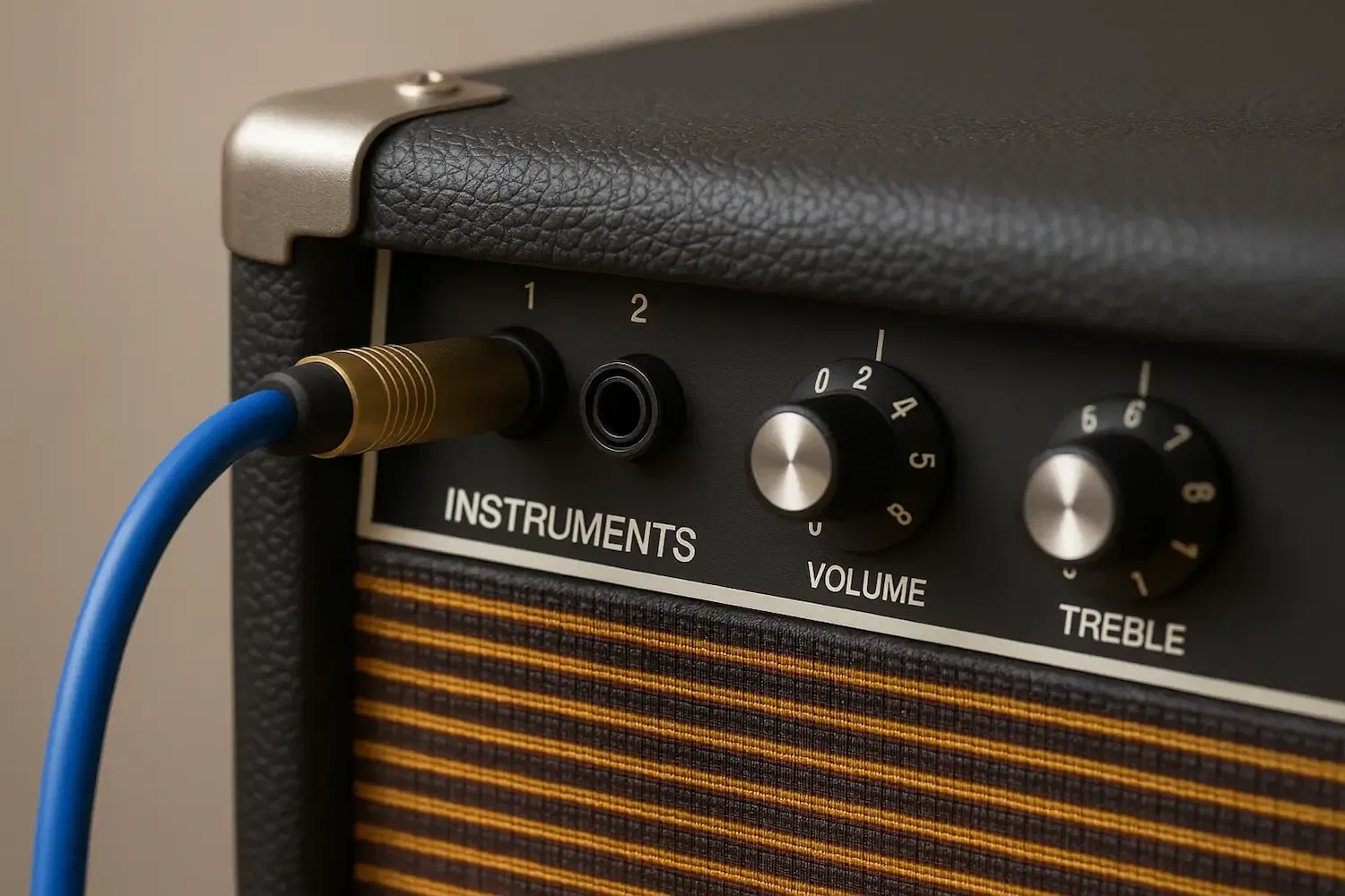
Using a non-inverting amplifier as a buffer is a simple yet powerful technique in analog electronics. By configuring the op-amp as a voltage follower, we get the best of both worlds: signal integrity and stage isolation, without the complexity of active gain control. Whether you're working with sensors, analog filters, or audio signals, the voltage follower is a vital tool to keep in your circuit design toolbox.
Related Topics:
Explore the theory, design, and practical applications of the non-inverting operational amplifier. Learn how it works, how to calculate gain, and where to use it in real-world circuits.
Learn how diodes are used as rectifiers in electronics. Understand half-wave and full-wave rectification with real examples and practical insights for beginners and hobbyists

Discover how piezo buzzers work and how to use them in your electronics projects. This guide explains their function, wiring, and applications as sound emitters and sensors.
Discover what flyback diodes are, how they work, and why they are crucial for protecting your circuits from voltage spikes caused by inductive loads like motors and relays.
Learn what coupling capacitors are, why they're essential in electronic circuits, how they block DC while passing AC signals, and key considerations when using them in your designs
Learn how to use a MOSFET as a simple electronic speed controller (ESC) for mini brushed DC motors. This beginner-friendly guide explains the circuit design, control method, and tips for safe operation
Or you can explore other categories
Electronics