Load Sensors
Understanding Load Sensors: How They Work and How to Use Them
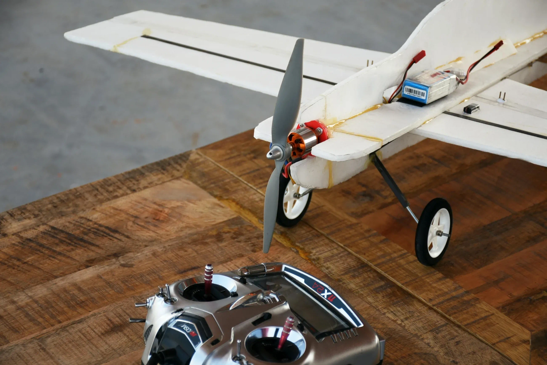
Have you ever wondered how digital weighing scales work? Or how industrial machines can detect how much pressure they’re applying? The answer lies in a clever little device called a load sensor—a small but powerful component that converts force into measurable electrical signals.
In this article, we’ll explore what load sensors are, how they work, and how you can use one in your own electronics projects.
1. What is a Load Sensor?
A load sensor, often referred to as a load cell, is a type of transducer. Its job is to convert mechanical force (like weight or pressure) into an electrical signal. This electrical signal is usually very small and needs to be amplified before it can be read by a microcontroller or data acquisition system.
These sensors are found in a wide range of devices:
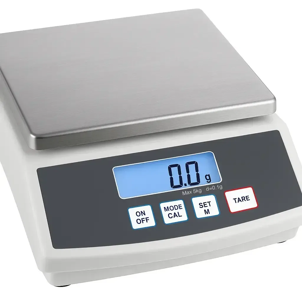
- Electronic kitchen scales
- Industrial weighing systems
- Smart luggage
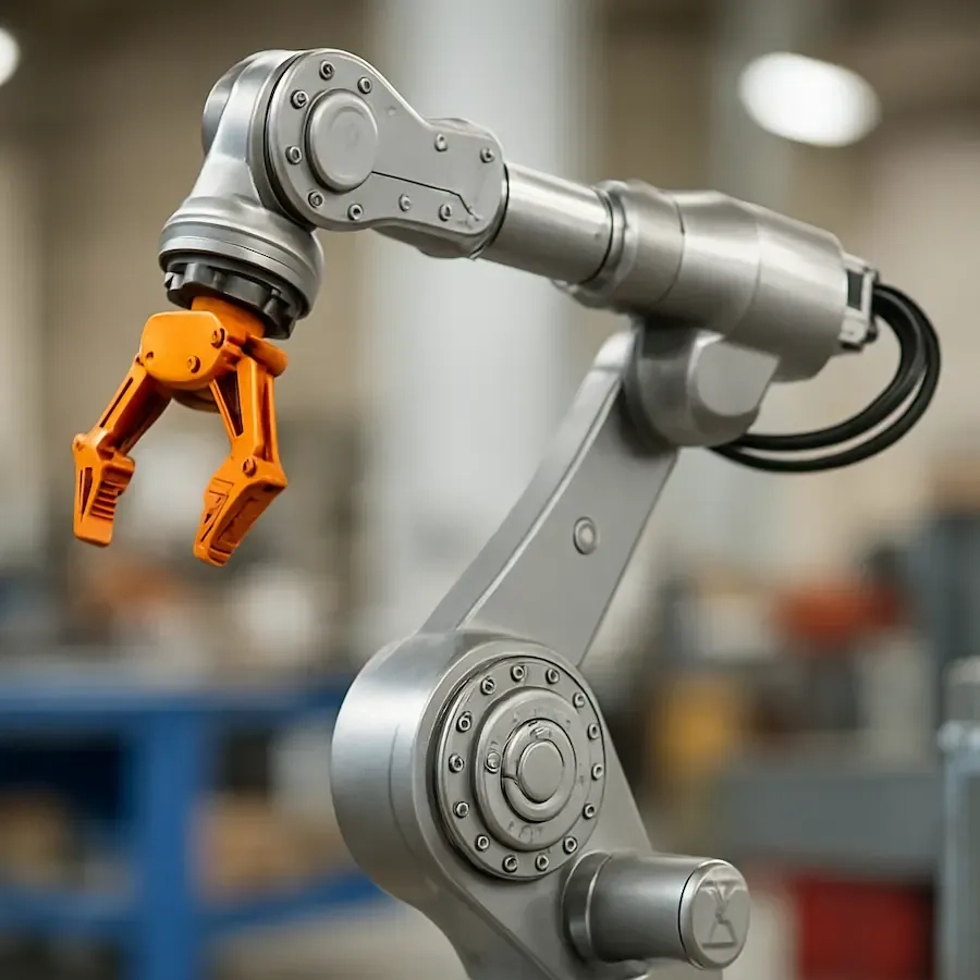
- Robotic grippers
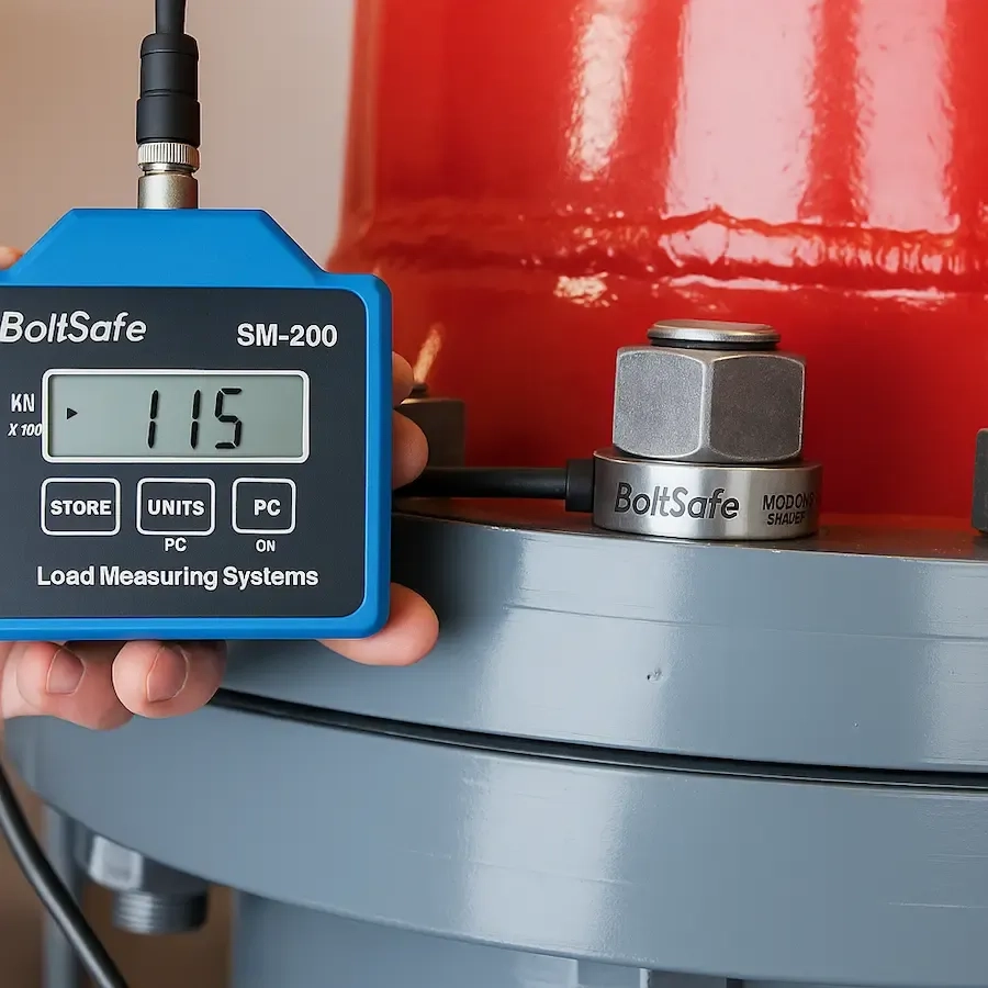
- Structural monitoring systems
2. How Do Load Sensors Work?
Most load sensors are based on a technology called the strain gauge. A strain gauge is a special wire pattern that changes its electrical resistance when it stretches or compresses. When a force is applied to the sensor, it causes a tiny deformation. This change is then translated into a change in resistance.
But here’s the challenge: the change in resistance is extremely small. That’s why strain gauges are arranged in a Wheatstone bridge configuration—this setup helps detect those tiny changes more accurately and gives a small voltage output that corresponds to the force applied.
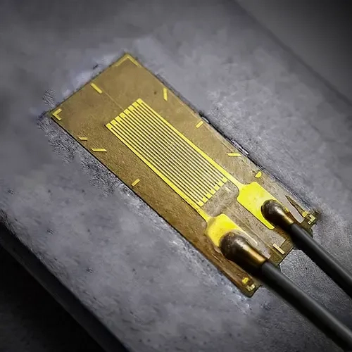
A strain gauge implanted in a metal beam
3. Common Types of Load Sensors
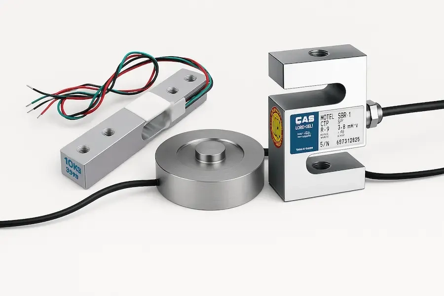
There are several types of load sensors, each designed for different mechanical applications:
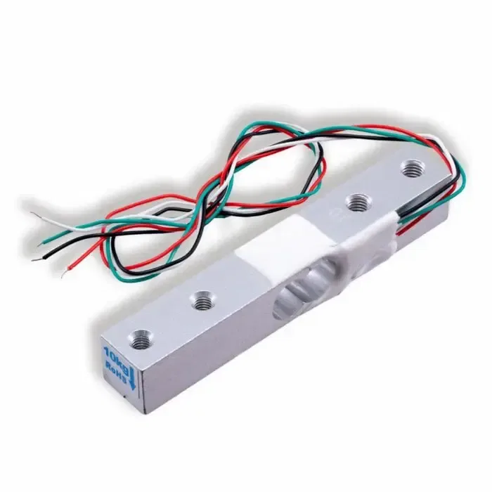
Single-Point Load Cell
Also referred to as a bending beam load cell, this is one of the most common load cell types used in DIY electronics and small-scale automation. It is a bar-type strain gauge load cell, often found on online marketplaces like AliExpress.
Key Features:
- Material: Aluminum alloy
- Wiring: 4-wire configuration (typically red, black, green, and white)
- Capacity: Ranges from 100g to around 200kg, depending on the model
- Structure: Features a drilled hole near the center with strain gauges glued around this region—typically arranged in a full Wheatstone bridge configuration
What Is It Used For?
This type of sensor is typically found in:
- Electronic scales (kitchen, postal, or jewelry)
- Weighing platforms and compact balance systems
- Robotics, such as force feedback in grippers
- DIY projects with microcontrollers like Arduino or ESP32
Why the Hole in the Middle?
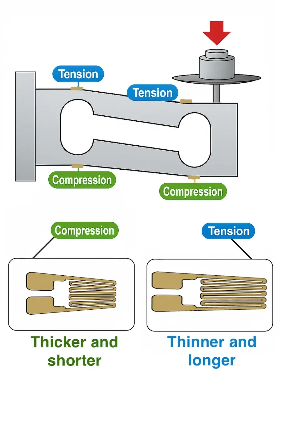
The hole is more than just a manufacturing feature—it’s a mechanical stress concentrator. When a load is applied to the sensor:
- The beam bends slightly, with the highest strain occurring near the drilled hole.
- The strain gauges detect these minute deformations.
- The resulting change in resistance is converted into a voltage signal through the Wheatstone bridge, enabling precise measurement of the applied load.
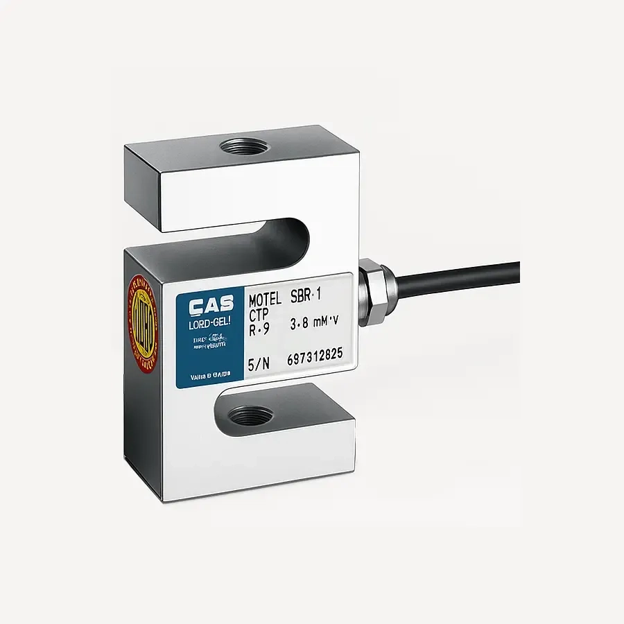
S-Type Load Cell
Shaped like an “S”, these are used for both tension and compression forces.
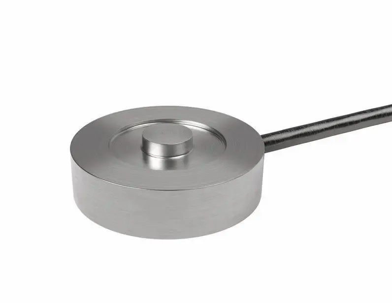
Button Load Cell
Compact and good for applications where space is limited.
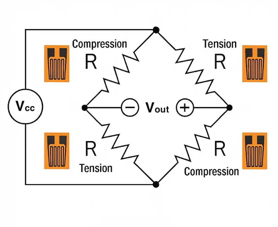
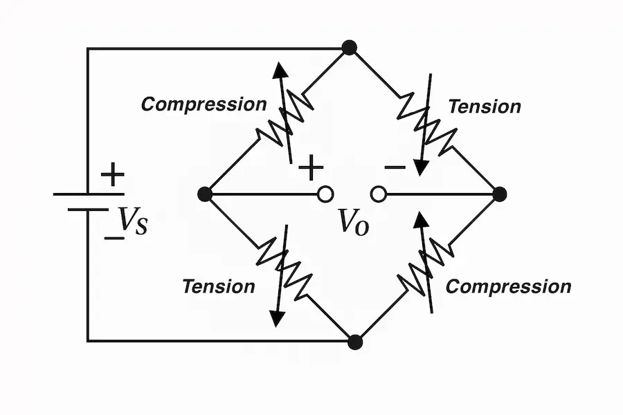
4. The Wheatstone Bridge Explained
To understand how a load sensor produces reliable electrical readings from mechanical force, we need to explore a key component inside it: the Wheatstone bridge.
What Is a Wheatstone Bridge?
A Wheatstone bridge is an electrical circuit used to measure very small changes in resistance. It consists of four resistors arranged in a diamond shape—two on the left, and two on the right. In the case of a strain gauge-based load cell, these resistors are actually the strain gauges themselves.
Here's how it works:
- When no force is applied, the bridge is balanced, and the output voltage is nearly zero.
- When a load is applied, the resistance of some strain gauges changes slightly.
- This unbalances the bridge and causes a small voltage difference to appear across the output terminals.
This voltage is proportional to the amount of strain, which in turn corresponds to the applied force.
Why Use a Wheatstone Bridge?
The Wheatstone bridge provides several advantages:
- High Sensitivity: It detects very tiny changes in resistance—perfect for strain gauges.
- Noise Rejection: It cancels out common voltage noise and temperature variations across the sensor.
- Linear Output: Most importantly, it gives a nearly linear relationship between applied load and voltage output, which makes calibration easier and readings more accurate.
Most load sensors use a full-bridge configuration, meaning all four resistors are active strain gauges. Some cheaper or compact models may use a half-bridge or quarter-bridge, but full bridges offer the best performance and stability.
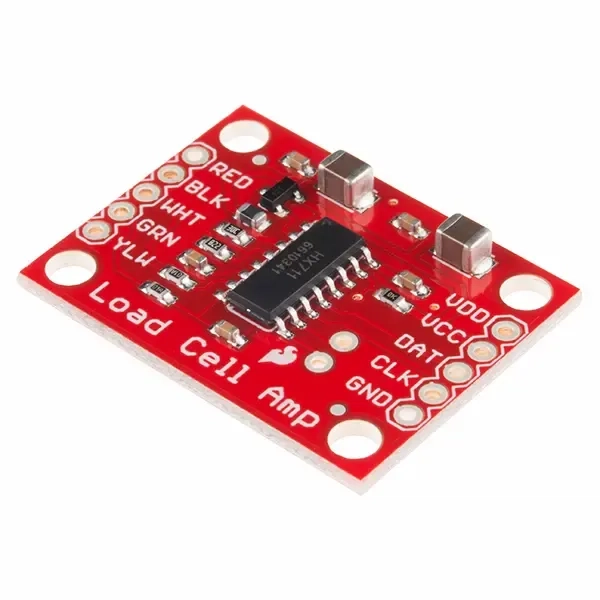
5. Signal Amplification: The Role of HX711
Load sensors produce a very low voltage signal (in millivolts). To read this signal with an Arduino or any other microcontroller, you need an amplifier and ADC (Analog to Digital Converter). A common and inexpensive module for this job is the HX711.
The HX711 amplifies the signal from the load cell and converts it into digital form, making it easy to interface with Arduino, ESP32, or Raspberry Pi.
6. How to Scale Your Load for Arduino Projects
Once you’ve connected your load sensor and the HX711 module to your Arduino, you’ll need to calibrate the readings to display actual weight values. This is done using the scale.set_scale(...) function.
Understanding scale.set_scale(...)
In the Arduino HX711 library:
1scale.set_scale(float scale_factor);
This function calibrates the sensor by applying a scale factor that converts raw ADC readings (unitless numbers) into real-world weight units like grams or kilograms.
Internally, calling:
1float weight = scale.get_units();
Performs this calculation:
1weight = (raw_value - offset) / scale_factor;2
Where:
- raw_value is the raw HX711 output
- offset is the zero point set by scale.tare()
- scale_factor is what translates the data into meaningful units
How to Calculate the Correct Scale Factor
Instead of guessing the scale factor by trial and error, you can calculate it using a known weight:
Steps:
- Zero the scale with no load:
1scale.tare(); // Set offset to zero
- Place a known weight (e.g., 500g) on the load cell.
- Get the raw unscaled value:
1float raw_value = scale.get_units(10); // average of 10 readings
- Calculate the scale factor:
1float scale_factor = raw_value / known_weight;2Serial.print("Calculated Scale Factor: ");3Serial.println(scale_factor);4
- Apply the scale factor:
1scale.set_scale(scale_factor);
Now, every call to scale.get_units() will return values in your preferred unit.
7. Using a Load Sensor with Arduino (Advanced Version with EEPROM)
This version of the Arduino code supports persistent calibration via EEPROM, and allows on-demand recalibrationwhen the push button is held during startup. It also uses a threshold to avoid printing small fluctuations.
Features:
- Press-and-hold on startup to enter calibration mode.
- Calibration is only performed when requested.
- EEPROM stores scale factor and a flag.
- Serial monitor used to enter known weight value.
- Clean display of weight with change detection.
Components Needed:
- Load cell (e.g., 1 kg)
- HX711 amplifier module
- Arduino board (Uno, Nano, etc.)
- Push button (connected to D4 and GND)
- Jumper wires and breadboard
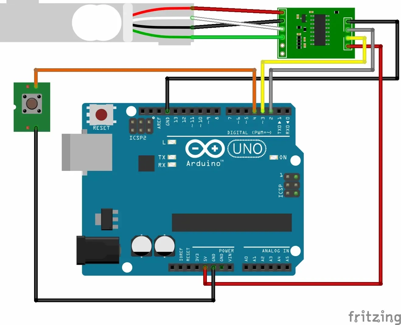
Wiring Overview:
- HX711 to Arduino:
- VCC → 5V
- GND → GND
- DT → D2
- SCK → D3
- Push Button:
- One leg → D4
- Other leg → GND
- No resistor needed (uses INPUT_PULLUP)
Note – HX711 Library Not Found?
If you’re getting a compilation error like:
fatal error: HX711.h: No such file or directory
That means the HX711 library is missing. To fix it:
Install via Library Manager:
- Open the Arduino IDE
- Go to Tools > Manage Libraries...
- Search for HX711
- Install HX711 by Bogdan Necula or Rob Tillaart
- Compile your sketch again
Arduino Code:
1#include <HX711.h>2#include <EEPROM.h>34#define DT_PIN 25#define SCK_PIN 36#define BUTTON_PIN 47#define EEPROM_ADDR 08#define EEPROM_FLAG_ADDR 19#define EPROM_SAVED_FLAG 0xA51011HX711 scale;12float scale_factor = 1;13float user_weight = 0;1415bool ButtonIsPressed() {16 return digitalRead(BUTTON_PIN) == LOW;17}1819void WaitPressButton() {20 while (digitalRead(BUTTON_PIN) == HIGH) {21 delay(100);22 }23}2425void WaitReleaseButton() {26 while (digitalRead(BUTTON_PIN) == LOW) {27 delay(100);28 }29}3031bool HasSavedFactor() {32 return (EEPROM.read(EEPROM_FLAG_ADDR) == EPROM_SAVED_FLAG);33}3435float WaitForSerialInput() {36 while (Serial.available() == 0) {37 // wait until user types a number38 }39 return Serial.parseFloat();40}4142void StartCalibration() {43 Serial.println("---------- Calibration Mode Started -----------");44 if (ButtonIsPressed()) {45 Serial.println("Release the button to start");46 WaitReleaseButton();47 }4849 scale.set_scale(1);50 scale.tare();51 delay(1000);5253 Serial.println("Place a known weight on the scale.");54 Serial.println("Then press the button to proceed");5556 WaitPressButton();5758 Serial.println("Enter the known weight value (in grams):");59 user_weight = WaitForSerialInput();60 Serial.print("You entered: ");61 Serial.println(user_weight, 2);6263 Serial.println("Calibrating, please wait...");64 float raw = scale.get_units(10);65 Serial.print("Raw value: ");66 Serial.println(raw, 6);6768 scale_factor = raw / user_weight;69 Serial.print("Calculated scale factor: ");70 Serial.println(scale_factor, 6);7172 EEPROM.put(EEPROM_ADDR, scale_factor);73 EEPROM.write(EEPROM_FLAG_ADDR, EPROM_SAVED_FLAG);7475 Serial.println("Remove any weight from the scale.");76 Serial.println("Then press the button to continue.");77 WaitPressButton();7879 Serial.println("---------- Calibration Completed -----------");80}8182void setup() {83 Serial.begin(9600);84 pinMode(BUTTON_PIN, INPUT_PULLUP);85 scale.begin(DT_PIN, SCK_PIN);8687 if (ButtonIsPressed() || !HasSavedFactor()) {88 StartCalibration();89 }9091 EEPROM.get(EEPROM_ADDR, scale_factor);92 Serial.print("Loaded scale factor from EEPROM: ");93 Serial.println(scale_factor, 6);9495 scale.set_scale(scale_factor);96 scale.tare();97 delay(1000);98 Serial.println("Scale is ready.");99}100101void loop() {102 static float lastWeight = 0.0;103 float weight = scale.get_units(10);104 if (weight < 0) weight = 0;105106 float threshold = 0.15;107 if (abs(weight - lastWeight) >= threshold) {108 Serial.print("Weight: ");109 Serial.print(weight, 1);110 Serial.println(" g");111 lastWeight = weight;112 }113114 delay(10);115}116
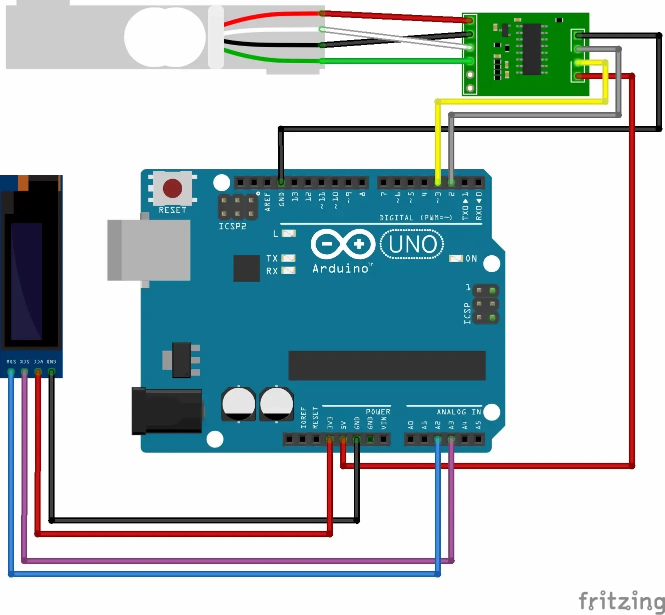
8. EEPROM Calibration + OLED Display (Improved Version)
In this version we removed the push button and used a 0.91‑inch SSD1306 OLED display
Wiring Overview:
we kept the connections of load sensor and the HX711 amplifier module unchanged while added a 0.91‑inch SSD1306 OLED display:
- VCC → 3.3V (Yes thats true the OLED can operate on both 5 and 3.3 V)
- GND → GND
- OLED SDA → A4
- OLED SCL → A5
No Serial Monitor Needed Anymore!
Thanks to the OLED display integration, in the following improvement, the Arduino is now fully standalone—once calibration is complete and saved, you no longer need to connect it to a computer or open the Serial Monitor to see the weight.
- After a one-time calibration, everything is saved to EEPROM.
- The OLED screen shows live weight continuously.
- This setup is perfect for portable or embedded applications like DIY scales, dispensers, or smart shelves.
Features:
- Calibration on-demand you optionally can keep the push button for on-demand calibration by holding the button while booting.
- Persistent scale factor stored in EEPROM.
- Live weight display using a 0.91‑inch SSD1306 OLED.
- Portable operation with no serial connection needed.
- Threshold filtering to avoid noisy fluctuations.
Arduino Code:
1#include <HX711.h>2#include <EEPROM.h>3#include <Wire.h>4#include <Adafruit_GFX.h>5#include <Adafruit_SSD1306.h>67#define SCREEN_WIDTH 1288#define SCREEN_HEIGHT 329#define OLED_RESET -1 // Reset pin not used1011#define DT_PIN 212#define SCK_PIN 313#define BUTTON_PIN 414#define EEPROM_ADDR 015#define EEPROM_FLAG_ADDR 116#define EPROM_SAVED_FLAG 0xA51718HX711 scale;19float scale_factor = 1;20float user_weight = 0;21222324Adafruit_SSD1306 display(SCREEN_WIDTH, SCREEN_HEIGHT, &Wire, OLED_RESET);2526void showProgress(unsigned long totalTime=500){27 unsigned long delay_t = totalTime/100;28 display.setTextSize(3);29 for(int i=0; i< 100;i++){30 display.setTextColor(SSD1306_WHITE);31 display.setCursor(i, 0);32 display.println(".");33 display.display();34 delay(delay_t);35 }36}3738bool ButtonIsPressed(){39 return digitalRead(BUTTON_PIN) == LOW;40}4142void WaitPressButton(){43 while (digitalRead(BUTTON_PIN) == HIGH) {44 delay(100);45 }46}4748bool HasSavedFactor(){49 return (EEPROM.read(EEPROM_FLAG_ADDR) == EPROM_SAVED_FLAG);50}5152void WaitReleaseButton(){53 while (digitalRead(BUTTON_PIN) == LOW) {54 delay(100);55 }56}575859float WaitForSerialInput() {60 while (Serial.available() == 0) {61 // wait here forever until user types something62 }63 float val = Serial.parseFloat();64 return val;65}6667void StartCalibration(){68 Serial.println("---------- Calibration Mode Started -----------");69 if(ButtonIsPressed()){70 Serial.println("Release the button to start");71 WaitReleaseButton();72 }737475 scale.set_scale(1);76 scale.tare();77 delay(1000);78 Serial.println("");79 Serial.println("Place a known weight on the scale.");80 Serial.println("then press the button to proceed");8182 WaitPressButton();8384 Serial.println("");85 Serial.println("Enter the weight value in the serial monitor:");8687 user_weight = WaitForSerialInput(); // Read float from serial88 Serial.print("You entered: ");89 Serial.println(user_weight, 2); // Print with 5 decimal places909192 Serial.println("Calibrating, please wait ...");9394 float raw = scale.get_units(10);9596 Serial.print("Raw value: ");97 Serial.println(raw, 6); // Print with 6 decimal places9899 scale_factor = raw / user_weight;100101 Serial.print("Calculated scale factor: ");102 Serial.println(scale_factor, 6);103 Serial.println("Saving scale factor to EEPROM: ");104 EEPROM.put(EEPROM_ADDR, scale_factor);105 EEPROM.write(EEPROM_FLAG_ADDR, EPROM_SAVED_FLAG); // flag as saved106107 Serial.println("Remove any weight off the scale");108 Serial.println("then press the button to proceed");109 WaitPressButton();110111 Serial.println("---------- Calibration Completed -----------");112}113114void screenSetup(){115 Wire.begin();116 display.begin(SSD1306_SWITCHCAPVCC, 0x3C); // 0x3C is the I2C address117118 display.clearDisplay();119 display.setTextSize(3);120}121122void displayWeight(float weight){123 display.clearDisplay();124 display.setTextSize(3);125 char displayBuffer[30];126127 dtostrf(weight, 5, 1, displayBuffer);128 strcat(displayBuffer, " g");129 display.setCursor(0, 0);130 display.println(displayBuffer);131132 display.display();133134}135136void setup() {137 screenSetup();138 Serial.begin(9600);139 pinMode(BUTTON_PIN, INPUT_PULLUP); // internal pull-up140 scale.begin(DT_PIN, SCK_PIN);141142 // enter caliration mode if scale factor is not set143 // or calibrate on demand when ardunio is powered while the button is down144 if(ButtonIsPressed() || !HasSavedFactor()){145 StartCalibration();146 }147148 EEPROM.get(EEPROM_ADDR, scale_factor);149 Serial.print("Loaded scale factor from EEPROM: ");150 Serial.println(scale_factor, 6);151152153 scale.set_scale(scale_factor);154 scale.tare();155 showProgress(1000);156157 Serial.println("Scale is ready.");158 displayWeight(0);159160}161162void loop() {163 static float lastWeight = 0.0;164 float weight = scale.get_units(10);165 if(weight < 0)166 weight = 0;167168169 float threshold = 0.15;170 float diff = abs(weight - lastWeight);171 if (diff >= threshold) {172173 Serial.print("Weight: ");174 Serial.print(weight, 1);175 Serial.println(" g");176 lastWeight = weight;177178 displayWeight(weight);179 }180181 delay(10);182}183
9. Real-Life Applications of Load Sensors
- Digital Weighing Scales: From kitchen scales to shipping scales.
- Smart Luggage: Detect weight without external scales.
- Industrial Automation: Monitoring press forces or filling weights.
- Robotics: Measuring grip force in robotic hands.
- Structural Health Monitoring: Detecting stress in bridges or buildings.
10. Practical Considerations
- Avoid Overloading: Every load sensor has a maximum capacity. Exceeding it can permanently damage the sensor.
- Stable Mounting: Load cells must be mounted securely and evenly to provide accurate results.
- Temperature Drift: Readings can vary slightly with temperature changes. Some load cells are temperature-compensated.
- Electrical Noise: Keep wires short and shielded to avoid interference in readings.
11. Conclusion
Load sensors are incredible tools that bring the physical world into your digital projects. Whether you’re designing a smart weighing system, a robotic gripper, or just experimenting with force measurement, understanding how these sensors work opens up a range of possibilities.
Try building your own digital scale using a load cell and HX711—it’s an educational and satisfying DIY project that gives you hands-on experience with force measurement.
Related Topics:
Discover how ultrasonic sensors work, their accuracy, and where they're commonly used in electronics and robotics. Learn about applications, limitations, and practical tips for using them in your projects
Explore the theory, design, and practical applications of the non-inverting operational amplifier. Learn how it works, how to calculate gain, and where to use it in real-world circuits.

Discover how 7-segment displays work, their internal structure, types (common anode vs cathode), and how to use them in Arduino projects. Perfect for beginners and electronics enthusiasts.

Learn how push buttons work in digital circuits, including pull-up and pull-down resistors, and how to handle switch debouncing using both hardware and software techniques. A must-read for electronics beginners and Arduino enthusiasts.
Resistors are key in electronics, from LED circuits to advanced projects. This guide covers their function, types, identification, and a relatable analogy to simplify learning.
Voltage divider explained simply! Learn the theory, formulas, and practical uses of voltage dividers in electronics circuits, Arduino projects, and sensor interfacing.
Or you can explore other categories
Electronics